Goal
Every watt a GPU server draws becomes heat that has to leave the rack. A rack of ordinary servers might draw a few kilowatts. A rack of GPU servers draws many times that, and at some point air cannot carry the heat away, so the cooling moves to liquid. For anyone who operates data center infrastructure this changes how racks are planned, commissioned and monitored.
This post is reading and arithmetic. The server figures come from NVIDIA’s DGX H100 documentation, the cooling approaches from ASHRAE’s technical committee paper, and the rest is physics with inputs marked as assumptions. It builds on the Part 6 power plan, which covered circuits, feeds and redundancy on paper.
Terms used in this post
- Rack density: the electrical power one rack draws, in kilowatts.
- CFM: cubic feet per minute, the unit servers use for airflow.
- BTU per hour: a unit of heat flow. One kilowatt is about 3,412 BTU per hour.
- Cold plate: a metal plate on a chip with liquid flowing through it, which carries heat away.
- Direct-to-chip cooling: liquid cooling with cold plates on the hot parts, while the rest of the server is still cooled by air.
- Immersion cooling: placing the hardware in a bath of non-conductive fluid.
- CDU: a coolant distribution unit, which transfers heat between a rack’s coolant loop and the building’s water.
- Manifold: the pipework in a rack that feeds coolant to each server.
- Water class: ASHRAE’s name for a range of facility water temperatures, written with the upper limit in degrees Celsius, such as W32 or W45.
- Thermal resistance: how many degrees a chip runs above its coolant per watt of heat, a measure of how good a cooling solution is.
What I built
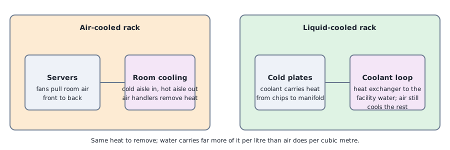
- A diagram of the two paths. An air-cooled rack and its room, and a liquid-cooled rack with its loop.
- A short calculator.
bench/part7-arithmetic.py powercomputes electrical power, heat and airflow for a rack of air-cooled servers, and compares the air and water needed to remove the same heat.
How it works
NVIDIA’s DGX H100 user guide gives the figures for one air-cooled eight-GPU server: a maximum of 10.2 kW, a heat output of 38,557 BTU per hour, airflow of 1,105 CFM front to back at 80 percent fan speed, and an operating temperature of 5 to 30 degrees Celsius. It has six power supplies in a 4+2 arrangement, so it can lose two and keep running.
Air carries little heat per volume, so moving more heat means moving more air, with bigger fans, higher speeds and more air handling in the room. Water carries far more heat per volume. NVIDIA’s rack-scale systems are described as liquid-cooled designs, and the DGX GB200 page calls its rack liquid-cooled, while the DGX B200 page lists an air-cooled eight-GPU system. The choice is made per product generation.
ASHRAE’s technical committee on high-density computing covers the approaches in its paper Emergence and Expansion of Liquid Cooling in Mainstream Data Centers. It describes cold plates, single-phase and two-phase immersion, and uses thermal resistance to compare solutions: as chips draw more power, the thermal resistance needed to keep them within their temperature limit is much lower than it was 10 or 20 years ago. The paper also renames its liquid cooling classes by upper temperature limit, W17, W27, W32, W40, W45 and W+, which is the vocabulary a facility team uses to agree on water temperatures with the equipment vendor.
Commands and results
The calculator takes the documented figures for one server. Four servers in a rack draw up to 40.8 kW and need 4,420 CFM of air by the documented figure. Using the physics of air, a rise of 15 K across the servers (assumed) needs 2.26 cubic meters per second, about 4,780 CFM, to carry 40.8 kW, which is close to the documented number. For the same load, water with a 10 K rise (assumed) needs 0.97 kg/s, about 58 liters per minute.
For a denser rack, I assumed 100 kW. Air would need about 5.5 cubic meters per second, around 11,700 CFM. Water would need 2.4 kg/s, about 143 liters per minute. The air figure is a very large flow to push through one rack, and the water figure is a pipe and a pump. That gap is the reason higher densities move to liquid.
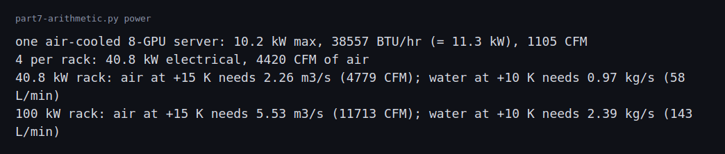
The 100 kW rack, the temperature rises and the four servers per rack are assumptions, chosen to show the method.
Challenges
- Power and cooling capacity are separate limits. A room can have electrical capacity for another rack and no cooling for it. Racks of this density have to be placed against both limits, and a hot spot shows up long before a breaker trips.
- Liquid adds new failure modes. Leaks, a failed pump, a clogged filter, air in the loop or coolant out of range all need alarms and a response plan. Leak detection and shutoff valves belong in the commissioning checklist, next to the power tests.
- Servers rely on cooling at once. A stopped coolant flow raises chip temperatures quickly, so monitoring has to alarm fast, and the servers need a safe throttle and shutdown behavior.
- Facility water has its own limits. Supply temperature, flow rate, water quality and pressure have to match what the equipment vendor specifies. The ASHRAE classes exist so both sides can agree on one number.
- A mixed room needs both systems. Cold plates take most of the heat, and the remaining parts of the server still need air. The air side of the room does not go away.
- I cannot practice this here. There is no liquid-cooled equipment in the lab. In the future I’m planning to purchase a hardware kit to help practice further.
Differences with a production setup
- Sources. The server figures are for one older, air-cooled system, and newer systems draw more. The pages linked above describe the current liquid-cooled products.
- Design. Real sites size power with the electrical chain from Part 6, and size cooling with the facility’s engineers, with margins for failure of a pump or a chiller.
- Monitoring. Production racks report coolant temperature, flow and pressure through the same management stack as power, and alarm on them. Inlet and outlet temperatures are tracked per rack, like the GPU temperatures from the monitoring post in Part 7.
- Standards. Class names, temperature ranges and connection standards come from industry bodies, with ASHRAE’s paper above as one example.
FAQ
Why does GPU density force liquid cooling?
Air carries little heat per volume. Past some density the airflow needed is more than racks and fans can deliver, and water carries the same heat in a pipe.
What is a cold plate?
A plate on a chip with coolant flowing through it. It takes the heat from the hottest parts directly.
Does liquid cooling remove the need for air?
No. The parts not on cold plates still need airflow, so the room’s air handling stays.
What is a CDU?
A coolant distribution unit. It passes heat from the rack’s coolant loop to the building’s water without mixing them.
What will change the most between these figures and a real rack?
The inputs. The server draw comes from vendor documentation, and the rack size and temperature rises are assumptions, so a real site’s loads, water temperatures and flow rates move every result.
Repeating with real hardware
Coming soon. With a real GPU rack I will log inlet and outlet temperatures and power over a burn-in, and compare the measured heat with the arithmetic above.
Next
Take the quiz to test your understanding: Part 8 quiz
Take the quiz to test your understanding: final quiz for Parts 1 to 8
Part 8 ends here for now. The next step is a run on real hardware, which needs a spend cap agreed beforehand.
For more on the electrical infrastructure that powers racks, from the generators and the grid connection to the hall and the rack, see the data center electrical design series, which starts by zooming out to the full chain.
Comments