3 Industry usedone · reading only
6 Bare metaldone
Emulated BMCs·Rack power plan·Drift and burn-in·NetBox inventory·Hardening and Secure Boot·Network boot with PXE·RAID and management network
7 Cloud + GPUemulated done · real run pending
AWS autoscaling·GPU fleet monitoring·GPU scheduling·NUMA topology
Goal
Training a large model on many GPUs spends a lot of its time moving data between them. Inside one server, how fast that is depends on how the GPUs are wired together. PCIe is the general-purpose bus that every device uses, and NVLink is NVIDIA’s dedicated GPU-to-GPU link. An NVSwitch chip joins many NVLinks so that every GPU in the server can reach every other GPU at full speed.
This post is reading and arithmetic, because the lab has no GPUs. The numbers come from NVIDIA’s own pages, linked in each place, and the calculation at the end uses them under stated assumptions. The aim is to know what the pieces are, to read the topology output that operations teams look at, and to see why the layout decides how jobs get placed.
Terms used in this post
- PCIe: the bus that connects CPUs, GPUs and network cards inside a server.
- NVLink: NVIDIA’s direct GPU-to-GPU link. A GPU has several links, and the figure NVIDIA gives is the total per GPU.
- NVSwitch: a switch chip for NVLink, so that GPUs reach one another through it instead of through a fixed wiring pattern.
- NVLink domain: the set of GPUs that can reach one another over NVLink. It is 8 GPUs in a single server and up to 72 in some rack-scale systems.
- Peer-to-peer (P2P): one GPU reading or writing another GPU’s memory directly.
- Collective: an operation that involves all the GPUs in a job, such as all-reduce, which sums a value across GPUs and gives everyone the result.
- NCCL: NVIDIA’s collective communication library, which chooses paths between GPUs and network cards.
- Topology matrix: the table that
nvidia-smi topo -mprints, showing the connection type for each pair of devices. - Host bridge: the PCIe root of a CPU, which traffic crosses when it has to go through the host.
What I built
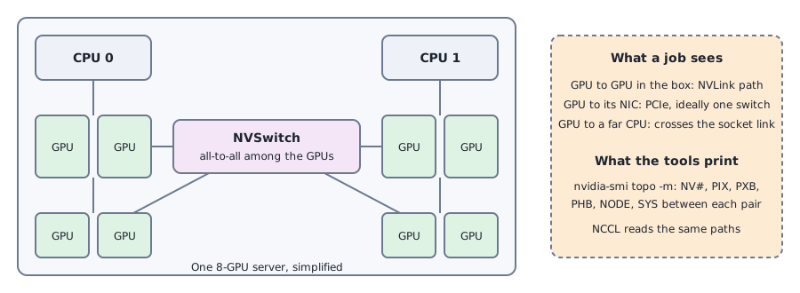
- A diagram of an 8-GPU server. It shows two CPUs, the GPUs, the NVSwitch fabric and the PCIe paths, with what each tool prints for each kind of path.
- A topology matrix I wrote by hand. It is an example to learn the format, with a legend taken from NVIDIA’s documentation. It is not output from a machine.
- A short calculator.
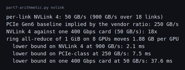
bench/part7-arithmetic.py nvlinkworks out per-link bandwidth and a lower bound for an all-reduce under three kinds of connection.
How it works
NVIDIA’s NVLink page lists the fourth generation, used with Hopper GPUs, at 900 GB/s per GPU over 18 links, and the fifth generation, used with Blackwell GPUs, at 1,800 GB/s. The same page gives an NVLink domain of 8 GPUs for a single server and 72 GPUs with the NVLink Switch system, and it compares the newest figure to PCIe by saying 3 TB/s is 12 times the bandwidth of PCIe Gen6. That ratio implies a PCIe Gen6 figure of about 250 GB/s, which I use below as the baseline.
A server with NVSwitch gives every pair of GPUs the same high bandwidth. NVIDIA’s DGX H100 user guide describes the system’s NVSwitch as providing 900 GB/s of GPU-to-GPU bandwidth. A server without NVSwitch can still have NVLink between some GPUs, such as pairs, and the rest of the traffic then goes over PCIe through a CPU. That difference is why two servers with the same GPUs can behave differently for a job that spans all of them.
For reading the layout, NVIDIA’s nvidia-smi documentation lists the connection types that topo -m prints. NV# is a bonded set of that many NVLinks. PIX is a path through a single PCIe switch, and PXB is a path through several PCIe switches without touching the host bridge. PHB goes through a PCIe host bridge, typically the CPU. NODE crosses the host bridges within one NUMA node, and SYS also crosses the interconnect between NUMA nodes. Part 7 covers the NUMA side.
NCCL uses the same vocabulary. Its environment variable reference describes NCCL_P2P_LEVEL as the maximum distance between GPUs at which NCCL will use direct peer-to-peer transfers, with the same levels spelled out as NVL, PIX, PXB, PHB and SYS. It also has NCCL_TOPO_DUMP_FILE, which writes out the topology NCCL detected, so a surprising choice can be checked against what NCCL believes the machine looks like.
Commands and results
Here is an example matrix for a four-GPU server without NVSwitch. I wrote it to show how the format reads. It is not from a real machine.
        GPU0  GPU1  GPU2  GPU3  NIC0  CPU Affinity  NUMA
GPU0     X    NV4   SYS   SYS   PIX   0-15          0
GPU1    NV4    X    SYS   SYS   PHB   0-15          0
GPU2    SYS   SYS    X    NV4   SYS   16-31         1
GPU3    SYS   SYS   NV4    X    SYS   16-31         1
NIC0    PIX   PHB   SYS   SYS    X
Reading it: GPU0 and GPU1 are joined by four NVLinks, and so are GPU2 and GPU3. Any other pair of GPUs, such as GPU0 and GPU2, goes across the socket interconnect (SYS), which is the slowest path. The network card is close to GPU0 (one PCIe switch) and a little farther from GPU1 (a host bridge), and far from the other socket’s GPUs. A scheduler that gives a two-GPU job GPU0 and GPU2 would work, but it would be a poor placement compared with GPU0 and GPU1. An 8-GPU server with NVSwitch would show NV18 between every pair of GPUs, which leaves only the network card and CPU affinity columns to read.
The arithmetic uses the vendor figures and one assumption: a ring all-reduce of 1 GiB of gradients on 8 GPUs, which moves about 1.88 GB per GPU. Per link, 900 GB/s over 18 links is 50 GB/s. The ideal time is 2.1 ms at 900 GB/s, 7.5 ms at the 250 GB/s PCIe baseline, and 37.6 ms at the 50 GB/s a single 400 Gbps network card carries. It ignores latency, protocol overhead and overlap with compute, so real times are longer and the ratios are the useful part. NVLink 4 is 18 times one network card’s bandwidth, which is the reason big jobs try to keep the chatty parts of a model inside one NVLink domain.
Challenges
- Two servers that look alike can place jobs very differently. A node with NVSwitch and a node with pairs of NVLinked GPUs both show “8 GPUs” in inventory. A scheduler that counts GPUs without reading the topology will mix them and give users uneven runs.
- A GPU can be near the wrong network card. If a job uses the GPU on one socket and the network card on the other, its traffic crosses the host. The matrix shows it as
PHBorSYSbetween the GPU and the card, and it appears as a slow node, not an error. - Topology can change after maintenance. A swapped riser, a card in a different slot or a disabled link changes the matrix without changing the GPU count. Comparing the matrix to a known-good one belongs in acceptance testing, next to the burn-in checks from Part 6.
- A degraded link is a health problem. NVSwitch systems depend on a fabric manager to configure the switches, and NVIDIA’s DCGM documentation describes monitoring the NVLinks that support the fabric. A dead link can leave the node working at reduced speed.
- This lab cannot show any of it. The lab has no GPUs, so the facts in this post come from NVIDIA’s documentation, and the example matrix is illustrative. In the future I’m planning to purchase a hardware kit to help practice further.
Production setup example: an NVL72 rack
Everything above is one server. The production form of the same idea is a rack, and NVIDIA’s DGX GB Rack Scale Systems User Guide describes it in enough detail to read as a design. The guide covers GB200 and GB300 racks. Each is an NVL72 rack, a 72-GPU NVLink domain, and the same layout applies to a single rack and to a SuperPOD of eight.
 Diagram: the parts of one rack and the three kinds of network that leave it.
What a node is here. The hardware chapter lists a rack as 18 compute trays, 9 NVLink switch trays, 2 top-of-rack switches for management and the power shelves. A compute tray is 1 RU and holds 2 Grace CPUs and 4 Blackwell GPUs, so one tray is one compute node: it runs its own operating system image, has its own BMC and appears to Slurm or Kubernetes as one machine with 4 GPUs. A rack therefore has 18 nodes and 72 GPUs, where a DGX H100 is one node with 8. The switch trays are not nodes that run jobs. Each one is a 1 RU box with 2 NVSwitch chips of 72 NVLink ports each, a BMC and its own operating system, NVOS.
The fabric. The compute trays and switch trays do not connect with cables you install. The guide says the NVLink fabric runs through connectors at the back of each tray into cable cartridges, a passive copper backplane up and down the back of the rack. Every GPU reaches the switch trays through it, and the switch trays make the 72 GPUs one memory-coherent domain. The networking chapter gives 1.8 TB/s of bidirectional bandwidth per GPU with NVLink 5.0, and the hardware chapter gives 57.6 Tbps of full-duplex bandwidth per switch tray. The two figures fit together under one assumption of mine: if each GPU has 18 links and each link and each switch port carries 400 Gb/s in each direction, then a GPU moves 18 x 400 Gb/s = 7.2 Tb/s each way, which is 0.9 TB/s each way and 1.8 TB/s in total, and a switch tray with 144 such ports moves 57.6 Tbps each way. In that case the rack has 72 x 18 = 1,296 GPU-side links and 9 x 144 = 1,296 switch ports, so every link has a port and nothing is oversubscribed.
Three networks leave the rack. The guide’s summary is that NVLink is the scale-up fabric inside the rack, InfiniBand is the scale-out compute fabric between racks, and Ethernet carries storage, management and external traffic. Each compute tray has 4 ConnectX NICs for the cluster network (400 Gb/s ConnectX-7 in the GB200 and 800 Gb/s ConnectX-8 in the GB300), 2 BlueField-3 DPUs for storage and management, and a 1 GbE port on its BMC. The guide names seven networks: externalnet, internalnet, dgxnet, ipminet, computenet, storagenet and failovernet. The out-of-band ipminet reaches every BMC, switch tray, power shelf and top-of-rack switch, which is the network the Part 6 posts built a small copy of.
The control plane runs on the switch trays. The software chapter lists what NVOS carries:
- The NVLink Subnet Manager discovers the NVLink topology, assigns each GPU and switch port a logical identifier, calculates and programs the forwarding tables, and programs partition keys for NVLink partitions.
- The Fabric Manager configures routing among the NVSwitch ports, sets up the GPU-side routing, coordinates with the GPU driver to initialize the GPUs, and monitors the fabric for NVLink and NVSwitch errors.
- NMX-Controller is the cluster application that runs the subnet manager and the fabric manager, and NMX-Telemetry collects telemetry from all the NVLink switches in the domain.
The compute trays run IMEX. A GPU in one tray cannot simply read the memory of a GPU in another tray, because they are different operating system instances. The Internode Memory Exchange service, nvidia-imex, runs on the compute nodes and handles the export and import of GPU memory across that boundary. Nodes in an IMEX domain talk to each other over the ordinary node network using TCP/IP and gRPC, and an IMEX channel, a /dev node, is what lets two CUDA processes share memory securely. For a scheduler this means a job that spans trays needs the same IMEX domain and channel on all of them, which is the reason the topology-aware scheduling of Part 7 matters at rack scale.
The libraries sit above that. NCCL, NVSHMEM and UCX use NVLink inside the domain and InfiniBand or RoCE between racks. NCCL is topology-aware, as the topo -m reading earlier suggests, and the guide says the NVSwitch hardware also performs part of the collective work in the network using SHARP. DCGM monitors the GPUs and the NVSwitches.
Power and cooling. The guide gives about 120 kW for a rack. Power shelves convert AC to nominal 50 to 51 V DC and feed a bus bar, with N+N redundancy across the shelves, and liquid runs through manifolds to cold plates on the CPUs and GPUs while the NICs and drives stay air-cooled. The power and cooling post and the electrical series cover those parts.
Bringing a rack up is a sequence. The guide’s cold reboot sequence is a list of waits and checks:
- Switch all power shelves off, wait three to five minutes for the capacitors to discharge, and ping every BMC and OS address to confirm nothing answers.
- Switch the shelves on, wait two minutes for the BMCs, and ping the BMCs.
- Wait two more minutes for the switch trays to boot NVOS, then provision them and, for a multi-node workload, start the NMX-Controller services and check them.
- Only then power on the compute nodes through their BMCs, wait five minutes, and ping them.
- Run the post-reboot checks:
nvidia-persistencedis running,nvidia-imexis active, all NVLinks are active, every GPU shows a fabric state of Completed with status Success, and the peer-to-peer topology shows OK for every GPU, resetting any GPU that does not.
A warm reboot skips the shelves. The compute trays are powered off through the BMC, the NMX-Controller is stopped and started again on the switch tray that runs it, the compute trays are powered on, and the same checks run. The order is the point: the fabric must be configured before the GPUs initialize against it, so the switch side comes up first.
What differs from the lab in this series. The lab nodes have no GPUs, so every NVLink figure here is a published one and the arithmetic is mine. The scheduling gap shows up in Part 7, where Slurm and Kubernetes each have a way to describe CPU and GPU placement.
FAQ
What does NVSwitch add over NVLink alone?
NVLink is the link. NVSwitch is the chip that joins links so every GPU reaches every other GPU at full speed, instead of only the ones it is wired to.
What do the letters in topo -m mean?
NV# is NVLink. PIX and PXB are PCIe paths through one or several switches. PHB crosses the CPU’s host bridge, NODE crosses host bridges within one NUMA node, and SYS crosses between NUMA nodes.
Why does a job care about the path between two GPUs?
Collectives like all-reduce move data between every pair on every step, so the slowest path in the group sets the speed.
Is NVLink bandwidth the same as network bandwidth?
No. The per-GPU NVLink figure is many times a single network card’s, which is why jobs keep the heavy traffic inside the NVLink domain and cross the network less often.
What will change the most between this reading and a real system?
The numbers. The bandwidths come from vendor documentation. A real system reports what its links and software actually achieve, which is what the topology output and a collective test would show.
Repeating with real hardware
Coming soon. On a server with several GPUs I will print the topology matrix, dump NCCL’s detected topology, run NCCL’s all-reduce test between the closest and the farthest GPU pairs, and compare the results with the arithmetic above.
Next
Take the quiz to test your understanding: Part 8 quiz
The next post, InfiniBand and RoCE, covers how servers connect to one another.
Comments