Goal
The interconnection post drew the substation: two transformers, a medium-voltage bus with a tie, and a line from the utility. The microgrid post described how the site separates and reconnects. Between them sits the protection system, the relays that decide in a few cycles whether a current is a fault, whether a transformer is healthy and whether the site is still connected to the grid. A site with generation and a battery adds a second job: it must not keep a section of the utility network energized after the utility has opened.
We work through the relays and settings for the 75 MVA transformer of the example site, and the anti-islanding arithmetic for its on-site plant.
Terms used in this post
- Relay function numbers: ANSI/IEEE device numbers name what a protective relay does. 50 is instantaneous overcurrent, 51 time overcurrent, 87T transformer differential, 87B bus differential, 27 and 59 undervoltage and overvoltage, 81 over and under frequency, 81R rate of change of frequency (ROCOF), 32 reverse power, 25 synchronism check, 86 lockout, 50BF breaker failure.
- CT: a current transformer that scales a primary current to about 5 A (or 1 A) for the relay.
- Percentage differential: a relay that compares the current entering and leaving a transformer or a bus and trips on the difference, with the trip threshold rising with the through current.
- Slope: the fraction of the restraint current that the differential current must exceed to trip.
- Inrush: the large, harmonic-rich magnetizing current that flows for a short time when a transformer is energized.
- Harmonic restraint: blocking the differential trip when the second harmonic content marks the current as inrush.
- Non-detect zone (NDZ): the range of conditions in which an anti-islanding method cannot see the island.
- ROCOF: the rate at which frequency changes, in Hz per second.
- Direct transfer trip (DTT): a communication signal from the utility’s breaker that trips the site’s generation.
- Recloser: a utility device that closes a line again after a fault, usually after a short dead time.
What I built
bmc/protection.py, with five parts: full-load currents and CT ratios, an instantaneous overcurrent check against inrush, a percentage differential applied to five cases, an anti-islanding table for the on-site plant, and the angle error when a recloser closes onto a live island. A two-panel figure. The settings are assumptions marked A in the script, which are textbook values and not a relay setting.
How it works
Currents and CT ratios
The 75 MVA transformer carries 314 A at 138 kV and 3,138 A at 13.8 kV. CTs are chosen so that full-load current is a few amperes in the relay and the ratio is a standard one above 125 percent of full load: 400:5 on the high side and 4000:5 on the low side, giving 3.92 A at full load on both sides. The two sides match, which is the point of choosing the ratios together.
Overcurrent and inrush
The time-overcurrent element (51) on the 13.8 kV incomer picks up at 125 percent of full load, 3,922 A, and its curve is coordinated with the feeders downstream as in the short-circuit post. The instantaneous element (50) has to sit above the transformer’s inrush and below the fault current. Energizing a transformer draws a magnetizing current of several times rating for a fraction of a second, and we use about 8 per unit as a textbook figure. A bus fault behind the 652 MVA source is 27,278 A, 8.7 per unit, so an instantaneous element set at 1.3 times inrush, 32,633 A, would never see the fault. With a 10 percent transformer the fault and inrush currents are the same order, which is why the transformer is protected by its differential element and the incomer overcurrent is time-delayed.
Percentage differential
The 87T compares the two winding currents after ratio and phase correction. Differential current is the difference, restraint current the average of the two magnitudes, and the relay trips when the difference exceeds the larger of a pickup and the slope times the restraint. With a pickup of 0.3 per unit and a slope of 25 percent, both assumed:
| Case | Idiff | Irest | Result |
|---|---|---|---|
| Load, ratio error 2% | 0.02 | 0.99 | restrains |
| External fault 8 pu, one CT reads 10% low | 0.80 | 7.60 | restrains |
| External fault 8 pu, one CT saturates to 60% | 3.20 | 6.40 | trips, wrongly |
| Internal fault 8 pu from one side | 8.00 | 4.00 | trips |
| Energization inrush 8 pu, one side only | 8.00 | 4.00 | would trip, blocked by second-harmonic restraint |
The third row is the classic problem. A CT that saturates on a heavy external fault produces a false differential. A second, steeper slope at high restraint, CT sizing for the maximum fault, and harmonic restraint on CT saturation address it. An SEL paper on inrush stability explains that harmonic restraint blocks the differential on inrush but can also delay operation for heavy internal faults, and that the unrestrained differential element is set just above the highest possible inrush so that a heavy internal fault trips even when the CTs saturate and block the restrained element.
Anti-islanding
A site with generation must not energize a section of the utility network that the utility has isolated. IEEE 1547 requires that when an unintentional island forms the resource detect it and cease to energize within 2 seconds. The NLR slides on preventing unintentional islands sort the methods:
- Passive local methods: over and under voltage and frequency (27, 59, 81) set as a window, with a non-detect zone between trip points, ROCOF, voltage phase jump and harmonic monitoring.
- Active methods: inject a small disturbance and watch for the response, such as impedance measurement.
- Communication-based methods: direct transfer trip from the utility breaker or sectionalizing devices, power line carrier and impedance insertion.
- Reverse power (32) for generators that are not exporting, and sync-check or undervoltage-permissive relaying at the utility breaker.
The slides also note that direct transfer trip often needs dedicated fiber or other communication infrastructure, which is costly to install and operate.
The non-detect zone is wide when a governor holds frequency. For an island with 105 MW of generators, an inertia constant of 1.5 s and 4 percent droop, the initial rate of change of frequency after islanding is the imbalance fraction times 60 Hz divided by 2H: 0.2 Hz/s for a 1 percent imbalance, 1.0 Hz/s for 5 percent, 5.0 Hz/s for 25 percent. A ROCOF setting of 0.5 Hz/s misses imbalances below about 2.5 percent. The settled frequency deviation is smaller: with droop, an imbalance below about 21 percent of rating leaves the frequency inside a plus-or-minus 0.5 Hz window, so a frequency window alone would not trip. Passive methods have large non-detect zones, which is why sites add transfer trip or a power-direction element.
Reclosing onto an island. A utility recloser closes a line again after a dead time of a fraction of a second. If the site’s plant is still running as an island, it drifts against the grid. At 0.5 s dead time a slip of 0.2 Hz gives 36 degrees of angle error at reclose and 0.5 Hz gives 90. Closing onto a live island out of phase stresses the generators and the transformer, which is why the utility requires transfer trip or a sync-check relay at its recloser.
Commands and results
python3 bmc/protection.py currents overcurrent diff island reclose
python3 bmc/protection.py plot protection.png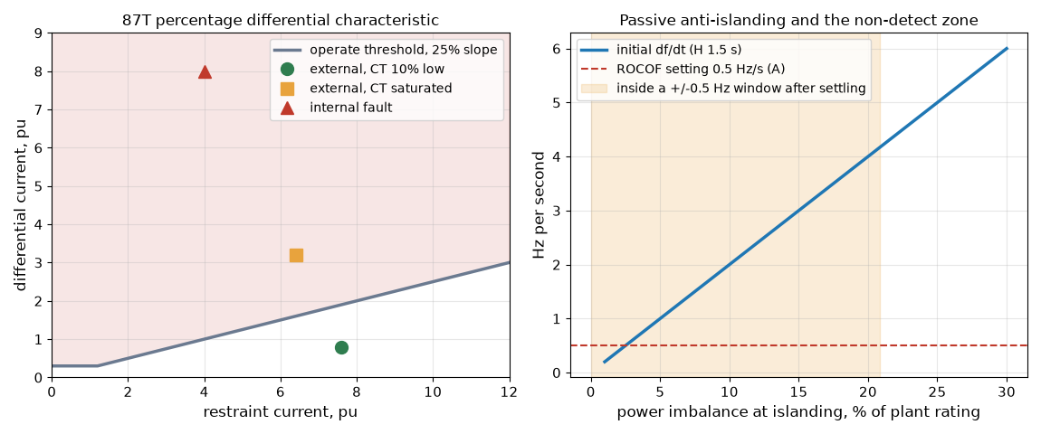
The left panel puts the five differential cases on the operate characteristic: the CT-error case sits below the line, the saturated CT and the internal fault above it. The right panel shows initial ROCOF rising linearly with imbalance, the 0.5 Hz/s setting crossing at 2.5 percent, and the shaded region where the settled frequency never leaves the window.
Challenges
- Inrush and the relay’s restraint settings can fight. Harmonic restraint set too sensitive blocks the differential on a real fault, and set too loose trips on energization. Settings are tested on recorded or simulated inrush, and the unrestrained element covers the heavy fault.
- CT saturation is a design problem, not a relay problem. The CT must carry the maximum through fault without saturating for the time the relay needs. A CT rating chosen for load current alone fails on the first heavy external fault.
- Protection must be validated in every configuration. Tie open and closed, one transformer out, island and grid-connected: each changes the fault current, and the settings are checked for each, as the inverter-fault-current numbers in the generator post show.
- Passive anti-islanding relies on a mismatch. If the site’s generation almost matches its load the frequency and voltage stay in the window, so detection by passive means fails exactly when the island is most stable. The site and the utility agree on transfer trip or an equivalent.
- Communication is part of the protection. A transfer trip channel is monitored and has its own failure handling, such as tripping the generation or blocking operation when the channel is lost.
- Settings are configuration-controlled. A relay setting changed during maintenance and never restored is one of the common causes of misoperation. Changes go through the same approval as a design change, and the as-found and as-left settings are recorded.
Production setup example
A substation protection design lists, for each zone, the relays and functions: line distance or differential, transformer differential with overcurrent backup, bus differential, breaker failure, and at the interconnection the voltage, frequency, ROCOF and reverse-power elements plus transfer trip when the utility requires it. A coordination study sets the curves and the utility reviews the settings that affect its network. Testing covers every function in the factory and again on site, with injection tests of the relays and an end-to-end test of the transfer trip.
The numbers here are teaching values. A real setting comes from a short-circuit study of the actual network, the relay manufacturer’s guidance, the CT and transformer test reports and the utility’s interconnection requirements.
FAQ
Why can’t a 50 element protect the transformer incomer?
With a 10 percent transformer the fault current and the inrush are the same order, so no instantaneous setting sits between them. The differential element, with harmonic restraint, protects the transformer.
What does harmonic restraint do?
It blocks the differential trip when the second harmonic content marks the current as inrush, and it has to be balanced against the risk of delaying a trip on a real internal fault.
Why is passive anti-islanding not enough?
If the generation and load nearly match, frequency and voltage stay inside the trip windows and nothing changes. Transfer trip or a power-direction element covers that case.
What is ROCOF good for?
It detects an islanding event by the rate of frequency change, which depends on the imbalance and the inertia. It misses small imbalances and can trip on grid events, so its setting is a compromise.
Why does the utility care about reclosing?
Closing a line onto an energized island out of phase damages equipment and can be dangerous to crews. Transfer trip or a sync-check relay prevents it.
What does this post not show?
A relay setting, a protection study or a test. It shows the functions, the arithmetic behind the main settings and why they are chosen.
Repeating with real hardware
Coming soon. The nearest repeat is to enter the same transformer and CT data into a relay manufacturer’s setting calculator and compare the slopes and pickups.
Next
Take the quiz to test your understanding: Electrical series quiz
The next post in this series covers power-system studies: load flow, motor starting, transient stability and EMT.
Comments