Goal
A design on drawings is a claim. Commissioning is how the claim gets checked before the load arrives, and it runs on documents. The basis of design says what the hall has to do and by what measure. The sequence of operations says what each piece of equipment does, in order, when something happens. The integrated systems test script says how to cause those things on purpose and what to record.
This post writes those three for the hall from the earlier posts, in the distributed design with three 1,200 kW blocks. Then I check the documents against a small model: the sequence of operations against its timing targets, and the test script against two sets of load pairs. One of them fails the test, which is the reason the test exists.

Terms used in this post
- Basis of design: the document that records the requirements and assumptions a design was made against, with the numbers a test will later be judged by.
- Sequence of operations: a step-by-step description of how the systems respond to an event, with timings.
- Integrated systems test: a test that causes real failures in the installed systems together and checks that the whole behaves as the design says. It follows tests of each component and each system on its own.
- Acceptance criterion: the measurable result that makes a test step pass.
- Transfer switch: a switch that moves a load between two sources, here between the utility and a generator.
- Walk-in: a gradual increase in the load a UPS rectifier or a generator takes on, to avoid a step.
- Depth of discharge: the share of a battery’s usable energy that has been used.
- Abort criterion: a condition that stops a test at once, such as a block above its rating.
- Level of commissioning: one stage of the checking, from factory tests through to integrated tests, commonly counted as five.
What I built
bmc/cx.py, a script that prints a basis of design of ten requirements, simulates the sequence of operations for the loss of a utility feed, and runs an integrated systems test script against the load model from the redundancy post.- The basis of design takes its figures from the earlier posts: a 2,400 kW critical load, three 1,200 kW blocks, 415Y/240 V to the racks, a five-minute UPS runtime at end of life, rack breakers that open alone, and branch-circuit meters with a missing-meter alarm. Two targets are new and assumed: the generator takes the load within 10 seconds, and the UPS batteries use no more than 25 percent of their usable energy during that event.
- A test script of five steps, T1 to T5, and a test record for it that I fill from the model.
How it works
Basis of design. Each requirement is a number with a source. A test step can only pass or fail against something written down before the test.
Sequence of operations. I wrote the loss of the utility feed to one block as a timeline. The UPS inverter carries the load from its batteries with no break. The transfer switch confirms the loss after 1 s and signals the generator, which reaches rated voltage and frequency at 8 s. The switch closes to the generator at 9.3 s, and the UPS rectifier takes the load back over a 20 s walk-in. When the utility returns and has been stable for five minutes, the load goes back to it, and the generator cools down for five minutes and stops. All the timings are assumptions.
Test script. T1 opens the utility feed to block A and checks the 10 s and 25 percent targets. T2, T3 and T4 open the output of UPS A, B and C in turn and check that no surviving block is over 100 percent of its rating. T5 stops generator A from starting during T1 and checks that UPS A rides at least five minutes at 800 kW. A real script also has start conditions, the data to record, abort criteria and a restore step for each.
Test record. For each step the script computes the result from the model: the battery energy for T1, the loading of the survivors for T2 to T4, and the runtime for T5. I ran it twice, with balanced load pairs of 800, 800 and 800 kW and with the unbalanced pairs of 1,000, 800 and 600 kW from the redundancy post.
Real commissioning documents from AI data centers, dissected. The Open Compute Project publishes commissioning material for the liquid-cooling side of AI halls, written by the companies that build and run them. Reading it against my three documents shows what a real one carries.
The pre-commissioning guideline for a row manifold. Guidelines for pre-commission preparation of technology cooling system (TCS) row manifolds in liquid cooled data centers is a 32-page OCP white paper from 2025. Its authors are from NVIDIA and Nalco Ecolab, and its acknowledgements list people from Meta, Vertiv, AMD, Dell and Intel. It covers the work that has to be finished before the cooling distribution units and racks are connected.

- It opens with its assumptions, which is a basis of design in miniature. Stainless steel pipework of at least grade 304, delivered clean and welded under inert gas, rack manifolds and distribution units not yet connected, contamination expected to be mostly inorganic dust. It states that commissioning the units and racks is out of its scope. Every number later in the document depends on these.
- Each number comes with its reason. The cold plates in current single-phase liquid cooling have flow channels of about 100 microns, so a particle that is harmless in a drain pipe can foul a chip’s cooling. The cleanliness criteria follow from that, in the same way my 10 s and 25 percent targets follow from what the load can tolerate.
- Every step has a source, a duration and a success criterion. The hydrostatic test is a proof-pressure test at 1.3 to 1.5 times the working pressure. Recirculation passes at least three system volumes through filters until the water has no visible particles, turbidity under 20 NTU and conductivity under 60 microsiemens per centimetre. Cleaning runs at least four hours, and passes when the filter’s pressure drop stops rising for an hour. Flushing recirculates at least eight system volumes and repeats until the conductivity is within 10 to 20 microsiemens of the fill water, or under 60, with final turbidity under 5 NTU. A script that says “run it until it looks fine” cannot be signed off. This one can.
- A change invalidates an earlier pass. Once the hydrostatic test is approved, the tested joints are not to be taken apart, and if any must be opened, the test is repeated. Water is not to sit unmoved for more than 24 hours without treatment, because of microbial growth. In my model, T1 to T4 would likewise need repeating after any change to the pairing of the load.
- Instruments and samples are written into the procedure. The crew records flow rates, pump speed and the pressure drop across the filters, and isolates a filter above 10 psi. A final water sample goes to a laboratory for conductivity, turbidity, pH and total aerobic bacteria, so the record of loop cleanliness does not rest on the crew’s own meters.
- It ends with a decision tree. The preferred path is to fill with glycol coolant at once, because glycol at the right concentration keeps microbes from growing. If the coolant is not ready, the loop is dried and held under a nitrogen blanket. During the fill, recirculation starts at about 90 percent full, and after at least three system volumes samples are taken from three places and tested for pH, turbidity, inhibitor level and glycol percentage. A real document plans for the case where the next stage is not ready.
The staged checks that follow. The OCP Liquid Cooling Integration and Logistics white paper has a section, 6.3, on the commissioning process for the cooling infrastructure, with contributors from CEJN, Cloud&Heat, Parker, nVent, CoolIT, Facebook, Vertiv and Wiwynn. It has five stages: electrical inspection, mechanical inspection, hydraulic and power circuits, controller set-up and complete start-up.
- The document is a checklist with room to write. The paper asks for a physical or online document for the commissioning team to mark off each check, with space allocated for notations. The record is part of the process and not something written afterwards.
- Load comes up in steps. Fill is progressive, with pauses to check for leaks, and flow and pressure are introduced gradually. The unit starts at lower flow than standard, to settle and vent, and only after the parameters are confirmed does it go up to the expected maximum. This is the same logic as the UPS walk-in in my sequence of operations.
- Alarms are tested by causing faults. At the end of complete start-up, several prescribed fault conditions are set to test the function of the alarms, and then the commissioning team is ready for handover to operations. It is the liquid-cooling form of my T1: cause the failure on purpose and record what the system did.
Where the power numbers come from. The Mt. Diablo disaggregated power rack specification (Microsoft, Meta and Google, October 2026) is a design specification and has no test procedure or acceptance section. It is the kind of document whose numbers a basis of design copies: a power supply without energy storage must hold up for at least 20 ms at full load, ride through sags to the ITIC curve and IEC 61000-4-34, and a rack with a battery backup unit must hold for 45 to 90 seconds at full load. They are rack-level figures, a layer below my five-minute facility UPS target. A commissioning test of a hall built on it takes them as the acceptance values.
The electrical side. OCP’s commissioning papers are on the cooling side, and the electrical test form I could open in full is a university standard, the Tennessee higher-education generator testing procedures form, section 26 08 30. It has the same shape as the OCP documents, with a header naming the unit by serial number and three columns of procedure, expected result and observations. Its expected results are blanks to be filled from the specification, which is the link back to a basis of design. It tests the generator cold start in intervals and repeats it, records with an analyzer instead of the generator’s gauges, steps the UPS load with specified and actual columns for voltage, frequency and THD, and ends with a test that opens the feeder to the transfer switch with the UPS at full load. It tests a single power train, generator to switch to UPS, so it has nothing like T2 to T4, where one block of a redundant design is opened and the survivors are checked for overload, and its text has no abort criterion. The University of Michigan generic sample commissioning plan shows how such forms are filed: a general tab with the systems list, the owner’s project requirements and basis of design, and the order and timing list, then one tab per system.
Factory and site acceptance for prefabricated equipment
When the switchgear, UPS or distribution is built in a factory as a skid or an e-house, the commissioning sequence splits in two and the document set has to say what each side proves. The vendors that sell these describe the same pattern: Vertiv lists a factory acceptance test, site acceptance support and level 5 commissioning on site, and Flex says structured factory acceptance and integrated systems testing catch issues earlier. What each test covers is a decision for the owner’s commissioning plan, and where a vendor’s test plan disagrees with the owner’s plan, the owner’s plan governs.
A working split, as a checklist in the commissioning plan:
| Check | Factory acceptance (FAT) | Site acceptance (SAT) |
|---|---|---|
| Nameplate and construction against the specification | yes: ratings, listing label, bus bracing, breaker types | spot check that what arrived is what was tested |
| Insulation and continuity | megger and hi-pot on the assembled equipment | repeat after shipping and after the field terminations are made |
| Protective relays and breakers | secondary injection of each relay, breaker timing | load the settings from the study and verify them on site |
| Interlocks and transfer logic | simulate every source-loss and restoration sequence | repeat with the real sources |
| Controls and monitoring | point-to-point to the controls interface, communications with the monitoring system | integration with the site’s actual system |
| Thermal and load | heat run if the product’s design requires it | infrared scan under load, |
| Transport damage | shock indicator readings, torque checks on bus joints | torque and inspection recorded before energizing |
| Integrated behavior | not possible without the site’s sources | the integrated systems test, with the real load bank |
Two points matter for the document set. First, each factory test needs a witness and a signed record that the site team can read, because a factory test no one reviewed is not a pass. Second, the interface list, which cable lands where, which breaker the controls expect to be closed and who owns the ground connection, is the document most likely to be incomplete, and a gap shows up on site, where fixing it is expensive. The new substation post lists the interface items for an MV e-house.
Commands and results
python3 bmc/cx.py bod
python3 bmc/cx.py soo
python3 bmc/cx.py ist
python3 bmc/cx.py plot cx-timeline.png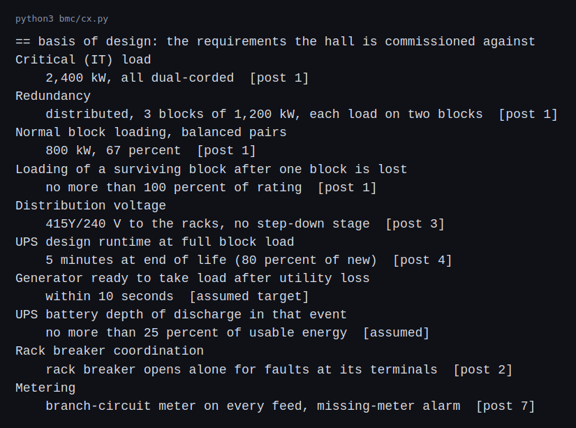
Ten requirements, each with a value and where it came from. Eight come from the earlier posts and two are assumed targets.
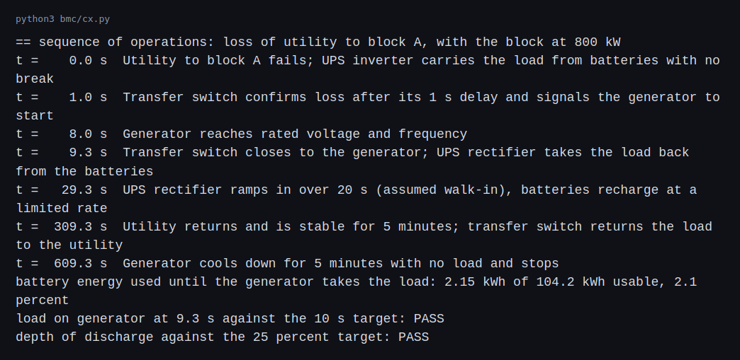
The generator takes the load at 9.3 s against the 10 s target, which passes with 0.7 s of margin. In the first 9.3 s the batteries supply 2.15 kWh at 800 kW, which is 2.1 percent of the 104.2 kWh usable energy, far inside the 25 percent target.
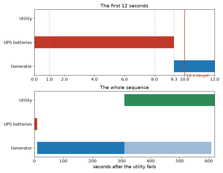
The batteries carry the block for the first 9.3 s. In the model the generator then carries it for five minutes until the utility is back, and runs another five minutes unloaded.
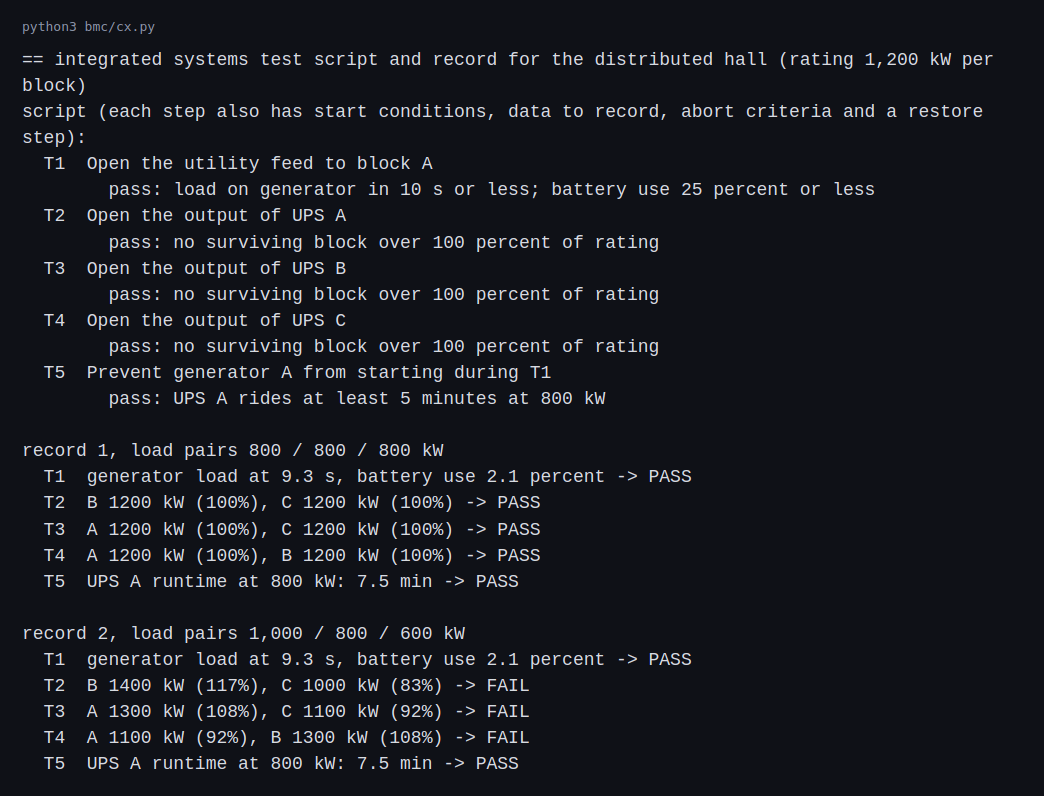
The script has five steps. With balanced load pairs all five pass. T2, T3 and T4 end at exactly 1,200 kW on each survivor, 100 percent, so the margin is zero. With the unbalanced pairs T1 and T5 still pass, because they depend on block A’s load, which is 800 kW in both cases. T2, T3 and T4 all fail: losing A puts B at 117 percent, losing B puts A at 108 percent and losing C puts B at 108 percent.
That is the same result as in the redundancy post, and now it is a test step with a pass criterion that someone runs on installed equipment with real load.
Challenges
- A test can only prove what a requirement says. T2 to T4 pass at exactly 100 percent. A requirement that says “no more than 100 percent” accepts a hall with no margin at all. Whether that is the intent has to be decided in the basis of design, before the test.
- The load in the test is not the load in operation. Integrated tests run with load banks or a partial load. The hall passes at 800 kW per block and later drifts to unbalanced pairs as racks are added, which is the failure in the second record. Tests have to be repeated after changes, or the check has to run continuously.
- Tests carry risk. Opening a UPS output on a live hall can drop the load if the design is wrong. A real script has abort criteria and a person with authority to stop it, and the test is staged to start with the least risky steps.
- Timings are measured in the field. The 10 s target depends on the generator, the transfer switch and their settings, which have to be measured on the installed equipment. A paper timeline cannot give the margin.
- Documents go out of date. The basis of design and the sequence of operations describe the hall on the day of commissioning. A later change to the equipment, to a setting or to the redundancy needs the documents changed, or the next operator works from a hall that no longer exists.
Differences with a production setup
Where a measurement, a standard, a datasheet or a vendor rating disagrees with a number in this post, the number in this post is the one that is wrong. The values most likely to differ are the 10 s and 25 percent targets and the 9.3 s transfer time, which are assumptions standing in for a real basis of design and measured timings.
- Process. Commissioning is run by a commissioning authority, with a plan, issues logs, witnessed tests, and sign-off at each level. The levels are commonly described as factory witness tests, delivery and installation checks, component start-up, system functional tests and integrated systems tests. ASHRAE Guideline 0 describes the process as verifying and documenting that the systems are planned, designed, installed, tested, operated and maintained to meet the owner’s project requirements (Archtoolbox’s summary).
- Acceptance testing. Switchgear, transformers, breakers and relays have their own acceptance tests, for example in the NETA specifications. The factory and site acceptance section above shows where those tests sit in the sequence.
- Generator and transfer standards. NFPA 110 covers emergency and standby power systems. It classifies a system by Level (how serious a failure would be), Type (the maximum time to transfer power, so Type 10 is 10 seconds) and Class (the hours it runs without refueling, so Class 96 is 96 hours) (Electrical Trader’s summary). My 10 s target follows the Type 10 idea but is an assumption for this lab.
- Real tests. Real integrated tests use load banks, instrumented capture of voltage, current and transfer times, and a test plan for each step. Mine are calculated values.
- Scope. A real script covers many more scenarios: cooling failures, controls and monitoring, fire and life safety, and the combinations of failures that the design claims to survive.
- Documents. A real basis of design runs to many pages and goes through owner and engineer review. Ten lines show the shape.
FAQ
What is the difference between a basis of design and a sequence of operations?
The basis of design says what the hall has to achieve and by which measure. The sequence of operations says how the equipment behaves, step by step, when an event happens.
Why simulate the sequence of operations?
To see whether the timings meet the targets and where the margin is. Here the generator takes the load at 9.3 s against 10 s, so the margin is 0.7 s.
Why does a test that passes at 100 percent still worry me?
It passes with no margin. A small change in load, or a drift in the load pairs, tips it over. The basis of design decides whether that is acceptable.
Why did the unbalanced hall fail only some steps?
T1 and T5 depend on the load of block A, which is 800 kW in both cases. T2 to T4 depend on how a failed block’s load splits among its partners, and that changes with the pairs.
Why test with a failure and not just inspect the equipment?
Each piece can be correct on its own and the whole can still behave wrongly, for example through a setting, a wiring error or an unequal load. Only a test of the system shows that.
What will change the most between these documents and a real commissioning?
The test results. Load bank tests, measured timings and sign-off decide whether the sequence works, and a test step will find design problems that the documents alone do not.
Repeating with real hardware
Coming soon. A small generator and transfer switch with a logger would let me measure a real transfer time and compare it with the sequence I wrote.
Next
Take the quiz to test your understanding: Electrical series quiz
The next post in this series covers arc-flash basics.
Comments