Goal
Racks that drew a few kilowatts now draw 100 kW, and designs for 1 MW per rack are being written. At that level the 54 V bus inside today’s racks needs tens of thousands of amperes, and the AC chain behind it has several conversion stages that each lose a few percent. Two proposals aim at both problems by distributing DC at 400 V or 800 V. NVIDIA describes an 800 V DC architecture, and Microsoft, Meta and Google have written a ±400 V rack specification through the Open Compute Project.
This post goes through what those two sources say, does the arithmetic that sits under the claims, and lists what changes for the people who protect, ground and work on such a system.
Terms used in this post
- HVDC: high-voltage direct current, used here for 400 V and 800 V DC distribution inside a data center.
- Bipolar: a DC system with a positive pole, a negative pole and a midpoint. A ±400 V system has 400 V from each pole to the midpoint and 800 V between the poles.
- Differential 800 V: the name the Open Compute specification uses for 800 V between the two poles.
- 54 V bus: the DC distribution inside today’s racks, from a power shelf to the servers.
- Sidecar power rack: a separate rack next to the IT racks that holds the AC-to-DC conversion, so the IT rack receives DC.
- Solid-state transformer: a transformer built from power electronics that converts between AC and DC and between voltages without a large iron core.
- Zero crossing: the moment an AC current passes through zero twice per cycle, which helps a breaker put out an arc. DC has none.
- Midpoint grounding: connecting the midpoint of a bipolar system to ground, directly or through a resistor.
- Low voltage (DC): in IEC terms, up to 1,500 V DC. Extra-low voltage is below about 120 V DC.
What I built
Nothing was built for this post. I read NVIDIA’s technical blog on its 800 VDC architecture, Microsoft’s blog on the Mt Diablo disaggregated power rack, and the table of contents, scope and efficiency sections of the Open Compute Mt. Diablo specification, version 1.0.0. bmc/dc.py does three pieces of arithmetic with assumed inputs: line current, conductor count and a conversion chain with assumed stage efficiencies.
How it works
What is proposed. Microsoft’s blog says today’s solutions convert AC to 48 V DC for the server trays, and that converting to 400 V DC, monopolar or bipolar, would improve efficiency. It describes a disaggregated design, with the power conversion in a separate rack from the compute. The specification, with Microsoft, Meta and Google as authors, is titled the Mt. Diablo Disaggregated Power Rack Specification and is effective 8 October 2026. It says the voltage is ±400 V DC or differential 800 V DC and that the choice follows mainstream electric-vehicle charging and battery technology. Its scope section describes rack power rising from 33 kW to hundreds of kW.
NVIDIA’s blog describes 800 V DC to support 1 MW IT racks starting in 2027. It says the architecture removes several AC-to-DC conversion steps by converting 13.8 kV AC grid power directly to 800 V DC at the data center perimeter, with 800 V DC busways along the row and direct 800 V input to the compute racks. It says the facility-level safety, standards and workforce training are new challenges and that the cost and safety of transformer-based and solid-state-transformer approaches are still being studied.
Arithmetic one: current. At 1 MW a three-phase 415 V AC feed carries 1,464 A per phase at a power factor of 0.95, an 800 V DC feed carries 1,250 A, and a 54 V bus would carry 18,519 A. At 100 kW the figures are 146 A, 125 A and 1,852 A.
Arithmetic two: conductor count. At one current density the copper is proportional to the number of conductors times the current. Three AC phases at 1,464 A come to 4,393 A-conductors, and two DC poles at 1,250 A come to 2,500. That is 43 percent less conductor cross-section, leaving out the neutral and the protective earth. Per conductor, a DC conductor moves 400 W per ampere and an AC phase moves 228 W, which is 76 percent more.
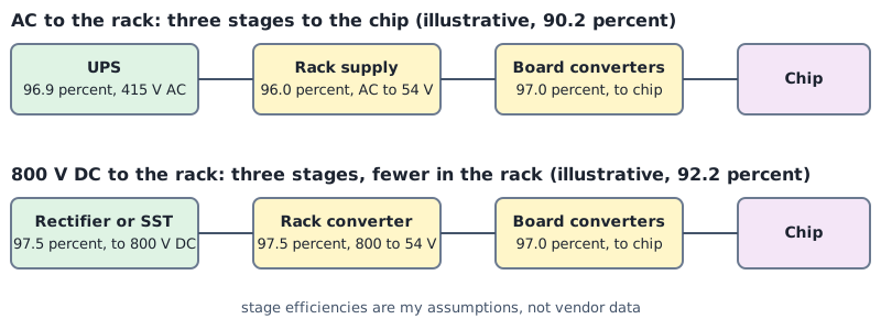
Arithmetic three: conversion stages. The stage efficiencies are assumptions chosen to show the effect of counting stages, and vendor efficiency curves replace them. An AC chain with a UPS at 96.9 percent (the figure from the UPS post), a rack power supply at 96.0 percent and board converters at 97.0 percent gives 90.2 percent. A DC chain with a rectifier at 97.5 percent, a rack converter at 97.5 percent and the same board converters gives 92.2 percent.
Commands and results
python3 bmc/dc.py current copper
python3 bmc/dc.py chain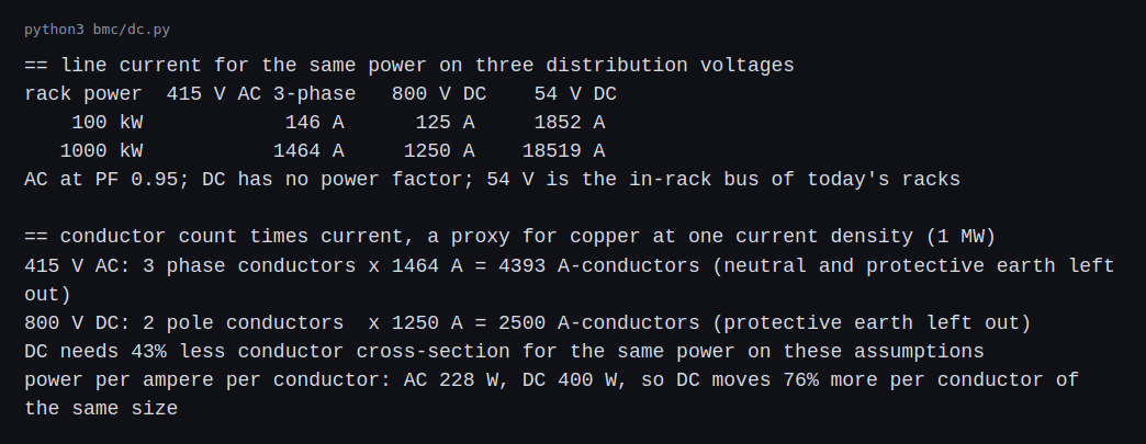
NVIDIA’s blog says row-level 800 V DC busways carry 85 percent more power through the same conductor size and cut the copper by 45 percent compared with 415 V AC. My arithmetic gives 76 percent and 43 percent under my simplifications: a power factor of 0.95, three AC conductors against two DC ones, and no neutral or earth. The 85 percent figure does not come out of these simplifications, and the difference is probably in what the blog counts.
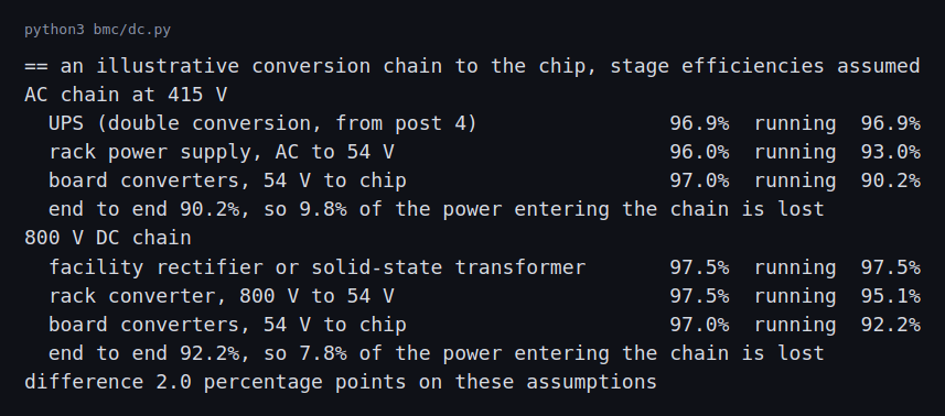
The DC chain comes out two percentage points ahead of the AC chain on my assumptions. The blog says up to 5 percent better end-to-end efficiency. My assumed stage figures are not vendor data, and a difference of that size depends on them. It also depends on which stages the AC baseline has, which is why the number of stages matters more than any one figure.
What changes in protection and grounding (reading)
- Interrupting DC. An AC breaker gets help from the zero crossing, twice per cycle. A DC current has none, so a mechanical breaker has to force the current down against a sustained arc, or the interruption is done by solid-state devices. NVIDIA’s 2026 800 VDC industry alignment white paper lists DC breaker selection and certification as a current engineering focus, so rating and testing of breakers at these voltages and currents is still being settled. Eaton’s 800 VDC white paper separates microsecond devices (solid-state and hybrid breakers) from millisecond ones (fuses, molded case breakers, air circuit breakers). Siemens’ paper on protecting DC data centers and ABB’s application paper on DC protection devices compare the device types in more detail.
- Fault current comes from power electronics. In an AC system the available fault current comes from transformers and generators and is large, as in the short-circuit post. Eaton describes a DC source fault in two parts. First comes a high current discharge from the capacitors in the source’s converters and in the converters in the racks. After a few hundred microseconds the source goes into current-limit mode, usually around 2 times full load current for at most a few seconds. NVIDIA’s paper adds that fault energy is often lower in converter-limited systems than in AC systems with utility and rotating machines behind them, depending on the source type and its control.
- Selective coordination. The goal is the same as in the short-circuit post: only the device nearest the fault opens. Eaton’s example is two 1500 A rack feeders under a 3000 A main. A fault at one rack has to trip its feeder and leave the main and the other rack running, and the same logic is needed inside the rack and between converters, inverters and solid-state transformers, not only between breakers and fuses. DC adds a problem that AC distribution rarely has. The capacitors in the rack converters draw a large inrush current when energized, which can trip or begin to melt an upstream device, so the downstream capacitance has to be known when a molded case breaker is selected and pre-charge circuits are usually added. Siemens gives two more reasons it is harder in DC. Fault current rises quickly, which pulls upstream devices into reacting, and an overcurrent comes with a voltage dip that matters for electronic loads if it lasts. With solid-state breakers coordination is largely built in, and with fuses the converters need active control and communication to coordinate. ABB describes the risk of the whole DC grid going out of service when upstream devices react in the first milliseconds. The Open Compute specification takes a simple route at the rack: each PDU output module, up to 400 kW with 50 kW or 100 kW cables, carries its own fuses and relays for over current. It does not set coordination curves between levels, and NVIDIA lists tap can protection coordination as open engineering work.
- Grounding choices. The Open Compute specification gives two ways to connect the ±400 V midpoint to protective earth, high resistance or solid, and for 800 V either a floating output with high-resistance grounding on the return or a single-ended output with the return solidly grounded. It requires a ground fault detector for either, and for a high-resistance midpoint the detector includes voltage balance detection. Its Appendix A lists the trade-offs. With high resistance grounding there is no arcing or fire risk when a pole shorts to earth, and the leakage current is too small to injure, but the system keeps running on the first fault and so the first fault can become a low priority. A second fault on the other pole is a fire or shock risk, the sensors need recurring calibration and testing because a defective one gives false security, and parallel sources lower the impedance to ground and raise the touch current. Equipment designed for high impedance grounding may also lack input fuses. With solid grounding, a fuse cuts power on a fault instead of a sensor, the faulted circuit is easy to identify and safety standards for low impedance grounding are clear. The costs are arcing until the fuse operates, a ground bond that has to carry the fault current until protection opens, and ground loops when several power racks are solidly grounded. NVIDIA’s 2026 paper compares four options for 800 VDC. A high-resistance midpoint gives balanced voltages to ground on both conductors, and a high-resistance return can detect return conductor faults late. A floating system needs insulation monitoring and fault locators because its fault current is so low. Solid grounding gives fast, sensitive detection and needs fast protection devices and a low-impedance ground bond. NVIDIA leaves the choice to system-level studies. Eaton adds how a resistance-grounded system is detected. Ground fault relays monitor each ungrounded conductor for voltage changes with respect to ground, and residual current monitors on each circuit find the faulted one. Siemens adds the personnel side. UL 943C Class E, for conductor-to-ground voltages above 300 V, asks for ground-fault interruption in about 850 µs at 400 V, which ground fault interrupters on the market do not meet, and with floating or high-resistance grounding continuous insulation monitoring replaces the fast interrupter.
- Arc flash. The method in the previous post is for AC. NVIDIA’s table of AC and DC fault behavior says a DC arc has no zero crossing to extinguish it, so connector design and arc detection become critical, and that converter-limited systems may reduce incident energy when current limiting and rapid fault isolation are in place. NVIDIA lists DC arc flash methodology and safety standards as ongoing work. Siemens notes that the IEEE 1584 studies are heavily based on AC, that NFPA 70E has DC guidance whose maximum-power calculation many consider overly conservative, and that arcing time and peak current dominate incident energy.
- Touch voltage. At 800 V between the poles, or 400 V from either pole to the midpoint, DC is within IEC low voltage but far above extra-low voltage. That means enclosures, interlocks and training, which NVIDIA lists as a challenge.
Challenges
- Standards are catching up. The Open Compute specification is at version 1.0.0 as of October 2026 and NVIDIA’s blog describes work in progress. A site that adopts a DC distribution early works with fewer settled references for components, connectors and tests.
- AC and DC halls will probably coexist (my inference). NVIDIA’s blog describes 800 V DC racks from 2027, and today’s halls are AC. A hall in transition runs two kinds of rack, two kinds of procedure and two sets of spares.
- Procedures and workforce. Work practices for energized DC at these voltages, lockout, testing for absence of voltage and emergency response, have to be written and taught. Equipment can be bought, and training takes longer.
- The metering and monitoring change. A DC system has no power factor and different sensors. The branch-circuit metering from the metering post needs DC meters, and the alerts need DC fault signals.
- Commissioning changes too. The integrated tests in the commissioning post, such as opening a UPS output, become tests of rectifiers and DC protection with different failure modes.
Differences with a production setup
Where a measurement, a standard, a datasheet or a vendor rating disagrees with a number in this post, the number in this post is the one that is wrong. The values most likely to differ are the stage efficiencies, the nominal voltages and the conductor counts, which leave out earth, and everything that comes from a vendor blog.
- Everything here is reading, and the efficiency chain uses stage figures I chose.
- Source quality. NVIDIA’s blog is the vendor describing its own architecture, and the claims of 85 percent, 45 percent and 5 percent are the vendor’s. They are claims to be checked against measurements or an independent test report.
- Specification reading. I read the table of contents, scope, efficiency, output protection and grounding sections, including Appendix A, of the Mt. Diablo specification. Its voltage tolerance figures are the ones a design uses, and the arithmetic here uses nominal voltages.
- Production status. NVIDIA’s 800 VDC blog targets 1 MW racks from 2027. Microsoft’s Mt Diablo blog describes a disaggregated design. Production setups today use AC distribution and a 54 V or 48 V rack bus.
- Studies. A real design would need DC short-circuit, protection coordination and arc-flash studies with software that models converters. ABB’s paper shows what such a model has to capture, with the fault current of an active rectifier worked out stage by stage for a pole-to-pole fault.
FAQ
Why would DC need less copper?
It has two conductors for the same power instead of three, and no power factor. At 1 MW the same current density needs 43 percent less conductor cross-section on my assumptions.
Why fewer conversion stages?
Today power goes AC to DC in the UPS path and then AC to 54 V in the rack. If the facility makes DC once and distributes it, the rack needs only a DC-to-DC step.
What does bipolar ±400 V mean?
The system has a positive pole at 400 V above the midpoint and a negative pole 400 V below it, so 800 V between the poles. Each pole is 400 V from ground when the midpoint is grounded.
Why is interrupting DC harder?
A DC current never crosses zero by itself, so an arc does not go out on its own. The breaker has to create the zero.
Is 800 V DC safe to work on?
It is in the IEC low-voltage class but above extra-low voltage, so it needs the same care as other low-voltage power equipment, with procedures written for DC. NVIDIA lists safety, standards and training as open work.
What will change the most between this reading and a real DC system?
The equipment. Real 400 V and 800 V DC gear has measured losses and its own protection design, which replace the arithmetic here.
Repeating with real hardware
Coming soon. There is no home-scale version of an 800 V DC rack. The nearest thing I could do is read the specification’s electrical sections in full and rework the arithmetic with its numbers.
Next
Take the final quiz to test your understanding of the whole series: Electrical series quiz
This is the last post in the series for now.
Comments