Goal
The redundancy post arranged power blocks for a whole hall. This one goes down to breakers. A short circuit on a rack cable should open the rack’s breaker and nothing else. When it opens the feeder breaker too, a whole row of racks goes dark for one bad cable, and the redundancy from the redundancy post is gone with it.
Two questions decide whether that works. How much current can a fault push through each point in the system? And will the breaker nearest the fault open before the ones behind it? I answer both on one 480 V path with textbook formulas, generic breaker curve shapes and assumed settings.

The drawing is the whole path: the transformer, the switchboard with its main breaker, the 400 A feeder to a panel, and the rack breaker. The circles mark the three breakers the rest of the post compares, and S, P and R mark the three places a fault is calculated.
Terms used in this post
- Short circuit: a fault where current flows around the load, so only the impedance of the source and cables limits it.
- Available fault current: the largest current a short circuit at a given point could drive. It is highest at the transformer and falls along each cable.
- Bolted fault: a short circuit with zero impedance at the fault itself, the standard worst case for these calculations.
- Interrupting rating: the largest fault current a breaker is rated to open safely.
- Time-current curve: a plot of how long a breaker takes to open at each current, on log axes.
- Long-time region: the sloped part of the curve, where the breaker opens after seconds because of an overload.
- Short-time delay: an intentional wait, a fraction of a second, before a breaker opens on a large fault, so a downstream breaker can act first.
- Instantaneous trip: opening with no intentional delay above a set current.
- Selective coordination: choosing breakers and settings so that only the breaker nearest a fault opens.
- Selectivity limit: the current above which two breakers in series can both open.
- Infinite bus: a source assumed to have zero impedance, which gives an upper bound on fault current.
What I built
bmc/sc.py, a script for one path: a 2,500 kVA 480 V transformer, a main breaker at the switchboard, a 400 A feeder with 100 m of 240 mm² cable to a panel, and a 30 A rack breaker in the panel with 30 m of 6 mm² cable beyond it. All data are assumptions.- A fault-current calculation at three points: the switchboard bus (S), the panel bus (P) and the end of the rack cable (R).
- A generic breaker model with a long-time curve, an optional short-time delay and an optional instantaneous trip, each with an assumed band of plus or minus 20 percent.
- Two cases. In case A all three breakers are thermal-magnetic style with instantaneous trips. In case B the main and the feeder have electronic trips with short-time delays of 0.4 s and 0.2 s.
- A selectivity check for each pair of breakers, and a plot of the curves for both cases.
How it works
Fault current. For a three-phase bolted fault the current is the line voltage divided by the square root of three times the impedance back to the source: I = V / (√3 × |Z|). The transformer impedance of 5.75 percent on a 2,500 kVA base is 5.30 mΩ at 480 V. I treated it as pure reactance, which is a common simplification for large transformers. Cable impedance adds in series at each cable. I ran two sources. An infinite bus gives the upper bound. A 500 MVA utility, also assumed, adds a little impedance in front of the transformer.
Interrupting rating. Every breaker has to be rated to open the fault current available at its own line terminals. The NEC covers this in 110.9, and it is checked device by device. That is why the number at the panel bus matters even though the transformer number is larger.
Selectivity. For two breakers in series, I compare the fast edge of the upstream breaker’s band with the slow edge of the downstream breaker’s band at each current. The upstream breaker must be slower at every current the downstream breaker can see. Where it is not, both can open, and that current is the selectivity limit.
What the cases mean. Case A is a common arrangement: small breakers with instantaneous trips. Case B gives the feeder and main a deliberate delay, so the rack breaker, with its instantaneous trip, always acts first.
Commands and results
python3 bmc/sc.py fault devices select
python3 bmc/sc.py times
python3 bmc/sc.py plot sc-tcc.png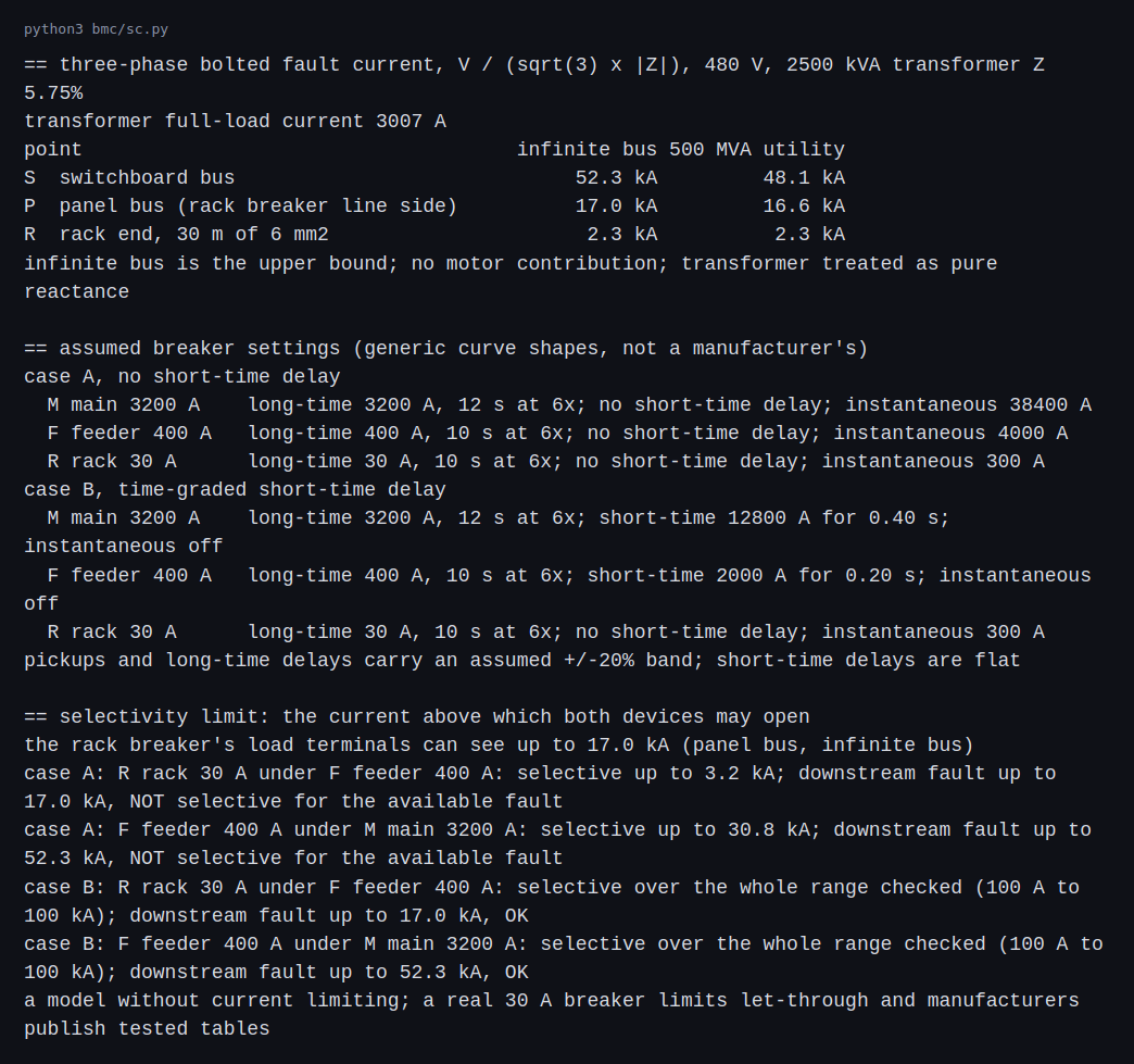
The infinite-bus fault current is 52.3 kA at the switchboard, 17.0 kA at the panel bus after 100 m of feeder, and 2.3 kA at the end of the 30 m rack cable. With the 500 MVA utility the numbers are 48.1, 16.6 and 2.3 kA. The switchboard equipment needs a rating above 52.3 kA on these assumptions, and the panel needs one above 17.0 kA.
Case A fails two selectivity checks. The rack breaker under the feeder is selective only up to 3.2 kA, and a fault at the panel bus can reach 17.0 kA. Above 3.2 kA the feeder’s instantaneous trip, set at 4,000 A with its band, can open as well. The feeder under the main is selective up to 30.8 kA, and the fault at the switchboard can reach 52.3 kA. In case B both pairs are selective over the whole range I checked, from 100 A to 100 kA.
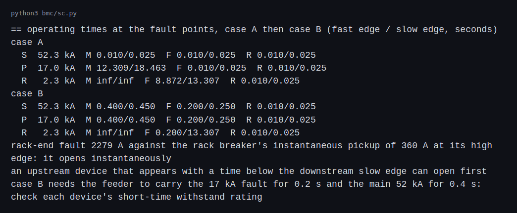
At the 17.0 kA panel fault in case B the rack breaker opens in 0.010 to 0.025 s, the feeder waits 0.20 s and the main waits 0.40 s. The far-end fault of 2.3 kA is well above the rack breaker’s instantaneous pickup of 360 A at the top of its band, so it opens at once. That is the check that a cable fault at the end of the run is still seen by the breaker.
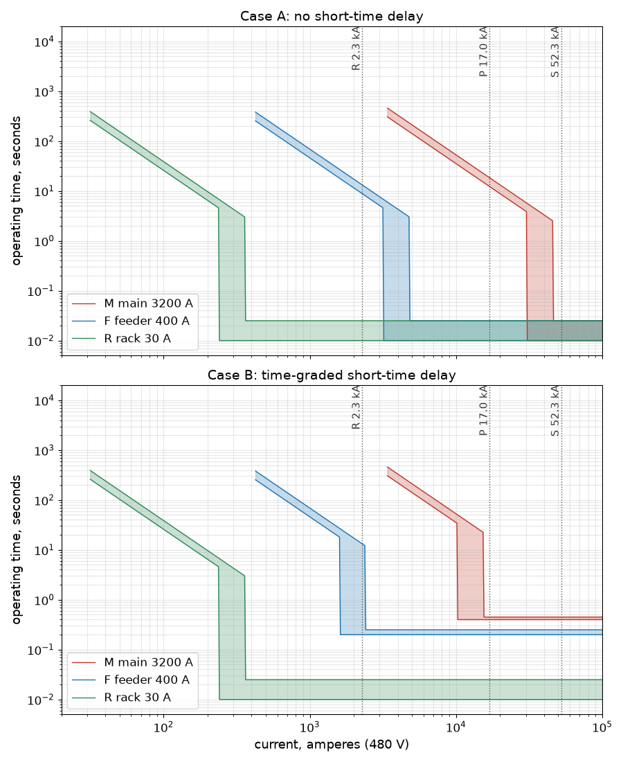
In case A the three instantaneous regions overlap, so there is no ordering at high current. In case B each breaker’s flat short-time section sits above the next one down.
The price of case B is in the first row of its times table. A fault at the switchboard bus is cleared by the main in 0.40 to 0.45 s. Case A would clear it in 0.010 to 0.025 s. A longer clearing time means more energy released if the fault is an arc, which is what the arc-flash post in this series is about. The feeder also has to carry 17 kA for 0.2 s and the main 52 kA for 0.4 s, so each needs a short-time withstand rating for that. I assumed none, and a data sheet would decide it.
Equipment ratings: UL 891 switchboard or UL 1558 switchgear
This section applies two product standards to my case study. Where the two disagree, the case study is the one that is wrong: a manufacturer’s listing, a nameplate rating or a design practice that contradicts a number here overrides it. The disagreements I can name are flagged where they occur and collected at the end of the section.
Case B delays the main breaker by 0.4 s so the feeder and rack breakers can act first. That delay has a price in the equipment. While the main waits, the switchboard bus and the main’s own bracing carry the full fault current. Two product standards draw the line, and the delay in case B decides which one passes.
Per the Consulting-Specifying Engineer comparison of the two standards, UL 891 switchboards are rated to withstand a short circuit for three cycles with no short-time rating. UL 1558 switchgear is rated for four cycles with short-time ratings of 30 or 60 cycles. Intertek describes UL 1558 as metal-enclosed low-voltage power circuit breaker switchgear for higher-duty systems and UL 891 as conventional switchboards, and says the two are not interchangeable.
| Check on the example path | Value | Three cycles (UL 891, no short-time rating) | 30 cycles (UL 1558, 65 kA short-time) |
|---|---|---|---|
| Fault current at the switchboard bus | 52.3 kA | within the 3-cycle withstand if the bus is braced for it | within the short-time rating |
| Main delay, case A (instantaneous, 0.025 s) | 1.5 cycles | passes | passes |
| Main delay, case B | 0.4 s = 24 cycles | fails: the bus has no rating for longer than 3 cycles | passes: 24 cycles is under 30 |
| Thermal duty, I²t at 52.3 kA for 0.4 s | 1,094 kA²s | 8 times the 3-cycle value of 137 kA²s | under the 65 kA for 0.5 s value of 2,113 kA²s |
So in this case study, the coordination that fixes the rack-fault problem in case B is only available if the equipment is rated to ride through the delay. Either the main is a UL 1558 power circuit breaker with a short-time rating, or the switchboard is specified with a short-time withstand rating that the manufacturer will certify. That connects selective coordination, a code requirement for emergency and legally required systems, directly to a purchasing decision.
Other differences that matter when evaluating a product on its merits and not on its datasheet:
- Breaker type. UL 1558 equipment takes only UL 1066 power circuit breakers, which are almost always drawout. UL 891 switchboards take UL 489 molded-case breakers, UL 1066 breakers or fused switches. CSE warns that on a UL 1066 breaker the instantaneous trip can be disabled, and a switchboard can then fail if the fault current is below the breaker’s instantaneous pickup, so the setting on the nameplate has to match the study.
- Maintenance. CSE says switchgear is compartmentalized by metal barriers between vertical sections, and drawout breakers let one breaker be serviced without de-energizing the downstream systems. A molded-case breaker that malfunctions generally has to be replaced whole.
- Space. CSE’s NEC 110.26 numbers: front-and-rear-access switchgear needs about 12.5 ft of total room depth, a wall-mounted front-access switchboard about 7 ft, and switchgear depth is at least 60 in against 24 to 60 in for switchboards. In a data center these feet come out of the electrical room that serves the white space.
- Cost. CSE calls switchboards generally significantly cheaper and gives no figure, and I use none here. In the redundancy post the distribution line is an assumed 250 dollars per kW. Swapping a block’s LV distribution from switchboard to switchgear moves that line, and the effect on the 2N, distributed and catcher totals can be rerun in
bmc/sld_cost.py. - Where each is used. Intertek lists data centers and other mission-critical facilities among the usual UL 1558 applications. A large share of data center designs still use UL 891 switchboards downstream, at the PDU and row level, where the available fault current is much lower and no delay is needed.
Where the case study departs from practice.
- The 0.4 s main delay is a teaching value chosen to make the selectivity gap visible. It is not a recommended setting. My own arc flash post shows what it costs: 15.55 cal/cm² at the switchboard, against 0.86 with an instantaneous trip. My inference is that a real design would shorten the delay, use zone-selective interlocking or a maintenance mode switch, or put the delay on the downstream side, and would not accept a 24-cycle hold on a 52 kA bus as the answer.
- The 3-cycle and 30-cycle figures are CSE’s general description of the two standards, dated 2022. A specific product is rated by its own listing and its tested short-circuit current rating. If a switchboard manufacturer lists a higher or longer withstand, or a switchgear line a lower one, the datasheet is right and the table above is wrong.
- The 65 kA short-time value is CSE’s illustration, not the rating of any product I looked at. The thermal comparison (2,113 against 1,094 kA²s) only shows the shape of the check.
- My fault currents come from a hand calculation with an assumed 500 MVA utility. A real utility value or a study model replaces them, and every pass or fail in the table can flip.
The review question for a submittal is concrete: for each device in the path, the rated interrupting current, the short-time rating and its duration, and the instantaneous setting must be at or above what the study shows at that point, and the listing standard on the nameplate has to match the specification.
What a study package contains
The numbers above came from a script. In a real project the same checks come from a model in SKM, ETAP or EasyPower, and the review is of the inputs as much as the outputs.
Inputs a reviewer asks for, and what happens when each is wrong:
- Utility available fault current and X/R. The utility supplies this in its interconnection data, usually as a minimum and maximum. Using the maximum for interrupting duty and the minimum for coordination and arc flash is the usual practice. The 500 MVA source I assumed gave a lower fault current at the bus than the infinite bus, and a real utility value moves every number below it.
- Transformer impedance and X/R from the nameplate or test report. The 5.75 percent in the example is a typical figure, and a manufacturing tolerance on impedance is worth a few percent on the fault current.
- Cable lengths and sizes from the construction documents. A study built from the early drawings is wrong after the cable pull changes. This is why the study is re-run at commissioning, and why the arc-flash labels are not final until then.
- Contribution from other sources. Generators, and UPS inverters, which limit their output to a small multiple of rated current, contribute in different ways. Their data comes from the vendor.
- Operating modes. Tie breakers closed, one source out, generator running. Each mode changes the fault current and the coordination, and an N+1 or 2N design has several. The study should list which modes it covered.
Outputs a package is expected to include: a device duty table (available fault current against each device’s interrupting and short-time rating, with a pass or fail), time-current coordination plots for each path from the source to the smallest load, protective device settings that the contractor enters and the commissioning agent verifies, and the arc-flash results from the arc flash post using the same model. The software is a calculator. The engineer’s work is the inputs, the modes and the judgment of what a failing line means for the design.
Challenges
- Fault current grows when the source changes. A larger transformer, a lower-impedance transformer or a second source in parallel raises the available fault current. Breakers that were rated above the old number may no longer be, and the number needs checking after any such change.
- A replaced breaker can break the coordination. A like-for-like swap with a different model has a different curve and different let-through. The 2023 edition of the NEC requires a recheck of emergency-system coordination when devices are replaced or the system is modified. NFPA’s TIA 23-11 quotes 700.32(B): where emergency system overcurrent devices are replaced, they shall be reevaluated to ensure selective coordination is maintained with all supply-side and load-side devices. 700.32(C) covers modifications, additions and deletions in the same way, and 701.32(C) and 708.54(C) carry matching rules for legally required standby and critical operations systems.
- Settings drift. A pickup raised to stop a nuisance trip, or a delay shortened, can undo a coordination that was correct on the day of commissioning. Settings need a recorded baseline and a check against it.
- Delay and arc energy pull in opposite directions. Coordination wants a delay on the upstream breakers. Arc-flash safety wants fault clearing as fast as possible. Case B shows the conflict at the main.
- A generator is a weaker source than the utility. When a site runs on generators the available fault current is lower, and a breaker that opens instantly on the utility may take longer or not trip. Settings need checking on both sources. A generator’s source impedance and the settings on that source are inputs to the study, which is why the study lists operating modes.
Differences with a production setup
- Study software. Fault current, device duty and coordination are done in software such as ETAP, SKM or EasyPower, with a model of the real network, then stamped by an engineer. The previous section lists the inputs and outputs of that package. My path is hand-built, one source and three devices.
- Manufacturer data. Real coordination uses each breaker’s published curves, and manufacturers publish tested selectivity tables, because a small breaker limits the current it lets through. My model has no current limiting, and that is why case A looks worse than a tested pair might.
- Motors and asymmetry. Motors add to a fault for the first cycles, and the first half cycle carries an offset that depends on the ratio of reactance to resistance. I used the symmetrical value with no motors.
- Cable and transformer data. I used assumed cable impedances and treated the transformer as pure reactance. A real study uses the data sheet and the cable table.
- Standards. NFPA 70, the National Electrical Code, covers interrupting rating in 110.9. Its Article 700 requires selective coordination for emergency systems, in 700.32 of the 2023 edition, and Article 701 has a similar rule for legally required standby systems. IEEE Std 551, the Violet Book, covers short-circuit calculation, and I saw it listed as inactive-reserved. IEEE Std 3002.3 is a recommended practice for short-circuit studies. On 110.9, the interrupting rating of an overcurrent device must be no less than the current available at the equipment’s line terminals, and 110.10 sets the same test for the short-circuit current rating of the equipment as a whole (IAEI’s explanation). IEEE 3002.3 is the current recommended practice for short-circuit studies, and covers new designs, existing systems and validation of the model.
- Which loads must coordinate. Whether a given data center load has to be selectively coordinated depends on how the code classifies it. Articles 700 (emergency) and 701 (legally required standby) require it, and so does Article 708 for critical operations power systems that a government agency or the facility’s engineering documentation designates (EC&M on Article 708). A data center’s own backup for its IT load is usually an optional standby system under Article 702, which EC&M’s comparison of the three describes as protecting property where life safety does not depend on the system, and for which it lists suitability for the available short-circuit current rather than coordination. A hall still has emergency or legally required loads such as egress lighting, and the authority having jurisdiction decides which loads fall in which class, so the IT load can fall outside the coordination rule (my inference), though a design may coordinate it anyway.
FAQ
Why does the fault current fall along the cable?
Each metre of cable adds impedance in series with the source. The same voltage drives the fault through a larger total impedance, so the current is lower. Here it falls from 52.3 kA at the switchboard to 2.3 kA at the end of a 6 mm² run.
Why is the infinite-bus case an upper bound?
A real utility has some impedance, which adds to the transformer’s and lowers the current. The infinite bus assumes none. With the 500 MVA utility the switchboard figure fell from 52.3 to 48.1 kA.
Why not make every breaker instantaneous?
Instantaneous trips act fast, which is good for arc energy. When two breakers in series both have them, a fault above the upstream one’s pickup can open both. That is case A.
Why does a time-current curve have a band?
Breakers are manufactured and tested to a tolerance. A safe comparison uses the slow edge of the downstream breaker against the fast edge of the upstream breaker.
Why does the far-end fault matter?
If the cable is long and thin enough, the fault current at its end can be too low for the instantaneous trip. In this path 2.3 kA is still well above 360 A, so the rack breaker sees it.
What will change the most between this example and a real study?
The device data. A manufacturer’s curves, the contribution of motors and generators and a stamped study replace the assumed values, and the coordination margins move with them.
Repeating with real hardware
Coming soon. There is no home-scale version of a 480 V distribution path. The repeat is the same path in study software with real data, or a published worked example reproduced by hand.
Next
Take the quiz to test your understanding: Electrical series quiz
The next post in this series covers busway, rack distribution and the choice between 415 V and 208 V.
Comments