Goal
Every earlier post in this series ended with a sentence like “a real design runs a study”. This post says which study and what it answers. A site with generation, a battery and a utility connection raises questions that a single formula cannot settle: what voltage does the load bus see at full load? How far does it dip when a chiller starts? Does a generator stay in step through a fault on the line? Does a capacitor bank resonate with the harmonics of the load? Each has a study, a tool and a set of input data.
We build a small version of four of them for the example site so the questions and the results have the same units as the real thing, and we say where the real study differs.
Terms used in this post
- Load flow (power flow): the steady-state solution for voltages and power flows in a network for a given load and generation.
- Short-circuit study: fault currents at each bus, as in the short-circuit post.
- Motor-starting study: the voltage dip and the time to accelerate when a large motor starts.
- Transient (dynamic) stability: whether machines stay in synchronism after a large disturbance such as a fault, over about the first several seconds.
- Critical clearing time: the longest fault duration after which the system is still stable.
- EMT: electromagnetic transient simulation, which solves the network and controls in the time domain at microsecond steps, including switching surges and inverter controls.
- RMS dynamics: a phasor-based dynamic simulation with time steps of milliseconds, used for stability studies.
- Locked-rotor current: the current a motor draws at standstill, several times its rating.
- Parallel resonance: the frequency at which a capacitor bank and the system’s inductance resonate, amplifying current or voltage at that harmonic.
- Large-load model: a dynamic model of a data center that describes how its load responds to voltage and frequency disturbances.
What I built
bmc/studies.py with four toy studies on a per-unit model of the utility, the 75 MVA substation transformer and a feeder: a load flow by fixed-point iteration, a motor-starting dip, a classical single-machine stability model with a bisection for the critical clearing time, and a resonance check. A two-panel figure. The inputs marked A are assumptions. These are teaching models of the kind found in a textbook, not replacements for the tools named below.
How it works
Which study answers which question
| Question | Study | Typical output | Typical tools |
|---|---|---|---|
| Is the voltage inside limits at full load and with a unit out? | Load flow | Bus voltages, losses, tap and capacitor settings | ETAP, SKM, EasyPower, PSS/E |
| What fault current must the equipment withstand and break? | Short circuit | kA at each bus | the same tools |
| Do the breakers trip in the right order? | Coordination | Time-current curves | the same tools |
| How far does the voltage dip when a large motor or a transformer starts? | Motor starting and step load | Minimum voltage and acceleration time | ETAP, SKM |
| Do generators stay in step through a fault, and does the island survive a load step? | Transient stability (RMS dynamics) | Rotor angle and frequency against time | PSS/E and equivalents |
| What do switching surges, inverter controls and resonance do? | EMT | Waveforms in the time domain | PSCAD, EMTP |
| Who may connect, and what upgrades are needed? | The utility’s interconnection studies | Required network upgrades | the utility’s tools |
Load flow
A load flow solves for voltages given power at each bus. For a radial site the solution is a short loop: guess the voltage, compute the current from the power, subtract the voltage drop along the impedance, repeat. The approximate result is the familiar one: the drop is roughly (R·P + X·Q)/V², so reactive power matters as much as real power in a network that is mostly reactance.
Motor starting
A motor starts with several times its rated current at a low power factor, and the voltage at the bus falls by about S_start / (S_sc + S_start) in per-unit terms, where S_sc is the short-circuit capacity at the bus. A site with a weak bus or many chillers starting at once has a bigger dip. The remedies are a soft starter, a drive, staggered starting and a stronger bus.
Transient stability
In the classical model a generator is a constant voltage behind a reactance, swinging against an infinite bus. During a fault the electrical power it can deliver drops, the rotor accelerates, and after the fault is cleared the machine either decelerates back or loses synchronism. The critical clearing time is the longest fault that still ends in recovery. Larger inertia, a stronger post-fault network and faster protection widen the margin.
EMT
An RMS study assumes the network is in a quasi-steady state at each step. An EMT study does not, which is why it is used for inverter controls, switching surges, ferroresonance and anything that depends on the waveform. It needs detailed device models from the vendor and takes more effort, so a design uses it where the RMS model cannot be trusted: a grid-forming battery, a large converter, a capacitor switching.
An EMT example: energizing a capacitor bank
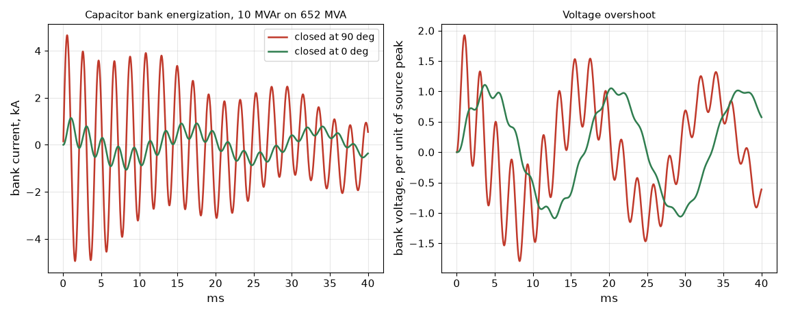
The smallest electromagnetic transient study is a switch closing onto a capacitor. The script’s emt mode energizes a discharged 10 MVAr bank on the 13.8 kV bus through the source inductance (0.77 mH from 652 MVA) with a series resistance of 0.05 ohm, and integrates the series circuit with a 10 microsecond step. The bank’s capacitance is 139 microfarads, and the circuit rings at 1/(2π√LC), 484 Hz. Closing at the peak of the source voltage gives a peak inrush of 4.9 kA, about 8 times the bank’s rated current of 418 A rms (591 A peak) and 1.92 per unit of voltage overshoot. Closing at a voltage zero gives 1.1 kA and 1.11 per unit. The instant of closing sets the result, and a phasor program cannot show it, which is why switching studies are done in EMT and why banks use synchronous closing or inrush reactors. The same method, with the controls of an inverter added, is how a grid-forming battery’s response is checked.
What a utility or a grid operator now asks of data centers
NERC’s incident review of the July 2024 load loss in Virginia lists the actions that transmission planners and operators should take: require dynamic response models of large loads in facility interconnection requirements, study the potential magnitude of load loss for faults and its impact on the system, take voltage-sensitive load loss into account in automatic reclosing schemes, monitor for load losses coincident with faults, and include ramp rates in operating agreements for connecting and reconnecting large loads. It lists open questions: whether large loads should be registered entities, whether reliability standards should change, which studies operators should perform and how a large load is defined. A data center that is interconnecting should expect to supply a dynamic model of its own behavior: how its UPS and controls respond to a voltage dip of a given depth and duration, and how it returns.
Commands and results
python3 bmc/studies.py loadflow motor stability resonance emt
python3 bmc/studies.py plot studies.png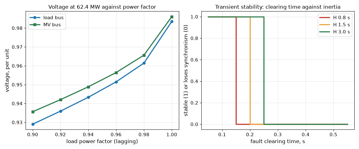
Load flow. The model has a 5,000 MVA utility, a 75 MVA transformer at 10 percent and an assumed feeder. At 62.4 MW and power factor 0.98 the MV bus is at 0.966 per unit and the load bus at 0.961, with 0.76 MW of loss. At power factor 0.95 the load bus falls to 0.947 and at 1.00 it rises to 0.984. Ten megavars of capacitors at 0.98 raise it to 0.979. A utility at 0.97 per unit drops the load bus to 0.930. The conclusion is the one a design review wants: this site needs reactive power support or a transformer tap changer to keep the voltage inside a band at full load.
Motor starting. The MV bus short-circuit capacity is 652 MVA with one transformer and 1,154 MVA with both. A 2.5 MVA chiller motor at six times locked-rotor current draws 15 MVA when started across the line and dips the bus by 2.2 percent with one transformer and 1.3 percent with two. Four starting at once draw 60 MVA and dip it by 8.4 percent and 4.9 percent. A soft starter at three per-unit cuts one start to 1.1 percent and a drive at 1.2 per-unit to 0.5 percent.
Stability. With a generator at 0.8 per-unit power, a pre-fault maximum of 1.8, 0.4 during the fault and 1.5 after it, the critical clearing time is 171 ms, about ten cycles, at an inertia of 1.5 s. At 0.8 s it falls to 125 ms and at 3.0 s it rises to 242 ms. The ten-cycle result means a breaker failure scheme that clears in more than ten cycles loses this generator.
Resonance. A 10 MVAr capacitor bank on the MV bus resonates at the harmonic h = sqrt(S_sc / Q_c): 8.1 with one transformer in service and 10.7 with both. The second case sits near the 11th harmonic, which rectifier loads produce, so a capacitor bank that is fine in one configuration is a problem in the other.
Challenges
- A study is only as good as its model. Load flow, short-circuit and stability results depend on impedances, ratings and controls that are often defaults until the equipment is bought. The study is repeated at each design stage and again with as-built data.
- Operating configurations multiply the cases. The tie open and closed, a unit out, the battery in and out, the utility at high and low voltage all change the results. The study matrix is written before the runs.
- A dynamic model of the load is new work. Data center loads respond to a voltage dip through UPS and controls, and a model that treats them as constant power misses the load loss that NERC describes. The owner owns the model and its validation.
- Inverter models are vendor-specific. An RMS model of a grid-forming battery may be a simplification of controls that matter for stability, so EMT results from the vendor’s model are asked for.
- A passing study is not a permission. The utility or the operator runs its own studies on its own network and may require upgrades, and a finding of a violation may change the site design late in the process.
Production setup example
A site study package includes a one-line diagram and data tables, a load flow with the base case and the contingencies, a short-circuit and coordination study, a motor-starting and step-load study, a harmonic and resonance study, a stability and island study, and for inverter-based resources an EMT study. The tools are the commercial ones named in the table, and models come from the equipment vendors. Reviews check the models against factory test data. The interconnection posts in this series cover the utility’s side.
The teaching models are single-line, per-unit and classical. A real study uses three-phase detail, vendor models of every machine and converter, and the actual network on the other side of the meter.
FAQ
What is the difference between RMS and EMT simulation?
RMS simulation treats the network as phasors in a quasi-steady state with time steps of milliseconds. EMT simulation solves the waveforms with steps of microseconds and can represent switching, inverter controls and resonance that RMS cannot.
Why does reactive power show up in a voltage study?
In a mostly reactive network the voltage drop depends on the reactive power as much as the real power. Supplying vars locally reduces the drop.
What does a critical clearing time tell you?
How fast the protection must clear a fault for a generator to stay in step. Slower clearing or lower inertia makes it shorter.
Why can a capacitor bank be a problem?
It resonates with the system inductance at a harmonic, and if that harmonic is one the loads produce, the bank amplifies it.
What does a data center owner supply for an interconnection study?
Load data, equipment ratings and, increasingly, a dynamic model showing how the load responds to voltage and frequency disturbances.
What does this post not show?
A study with real data or a commercial tool. It shows what each study asks and the size of the answers for the example site.
Repeating with real hardware
Coming soon. The nearest repeat is to run the same site in an open-source power-system package, or a vendor trial of a commercial tool, with the same impedances.
Next
Take the quiz to test your understanding: Electrical series quiz
The next post in this series covers vendor diligence, energy-services terms and bridging power.
Comments