Goal
Whether the rack has power is the first question. Three others come after it. Where are the neutral and ground tied together? How much current flows in the neutral wire of a three-phase system feeding server loads? And how much does the current those servers draw distort the voltage everyone else on the bus sees?
This post works through each with arithmetic on the 480 V path from the earlier posts. I follow the neutral current from unbalanced loads, then from rectifier-type loads, look at what harmonics do to a transformer and to the voltage at the bus, and finish with what grounding the system through a resistor changes about the first ground fault.
Terms used in this post
- Neutral: the conductor that carries the return current of single-phase loads in a four-wire three-phase system. In a balanced system with linear loads it carries nothing.
- Bonding: connecting the neutral to the grounded metal of the equipment. In a grounded system this is done at one point.
- Separately derived system: a system whose power comes through a transformer or generator with no direct connection of its neutral to another source, such as the secondary of a PDU transformer.
- Harmonic: a component of the current or voltage at a whole-number multiple of 60 Hz. The 3rd harmonic is 180 Hz and the 5th is 300 Hz.
- Triplen harmonic: a harmonic that is a multiple of three, such as the 3rd or 9th. These are in phase on all three phases.
- THD: total harmonic distortion, the combined size of the harmonics divided by the fundamental.
- Power-factor correction: circuitry in a power supply that makes its input current closer to a sine wave in phase with the voltage.
- K-factor: a number that expresses how much extra heating a transformer gets from a harmonic-rich load. It is 1.0 for a pure sine.
- High-resistance grounding: grounding the neutral of a system through a resistor that limits a ground fault to a few amperes.
- Point of common coupling: the point where a customer’s system connects to the one other users share, where distortion limits are judged.
What I built
bmc/pq.py, a script with four parts: neutral current from unbalanced loads, harmonics from two assumed supply types, voltage distortion from the transformer reactance, and ground fault current with a neutral resistor.- Two assumed current spectra for server power supplies. The older type has no power-factor correction and the other has active correction. These are shapes I chose, not measurements.
- A plot of three phase currents with 3rd and 5th harmonics and the neutral current that results.
How it works
Unbalance. With three single-phase loads, the neutral carries the phasor sum of the three phase currents, 120 degrees apart. For currents a, b and c the result is the square root of a² + b² + c² − ab − bc − ca.
Triplen harmonics. The 3rd harmonic of each phase is in phase with the 3rd harmonics of the other two, so in the neutral they add up instead of cancelling. Neutral current from rectifier-type loads is three times the 3rd harmonic current of one phase, combined by the root of the sum of squares with the 9th.
Heating. Harmonic currents add to the rms current and heat a transformer more than the same fundamental current would. The K-factor is the sum over all harmonics of the square of each share of the rms current times the square of the harmonic order.
Voltage distortion. A harmonic current I_h flowing through the source reactance gives a voltage of I_h × h × X, because reactance rises with frequency. I used only the transformer reactance of 5.30 mΩ per phase and left out the 3rd and 9th, because in a delta-wye transformer their currents circulate in the delta.
Grounding. In a grounded system the neutral of each separately derived system is bonded to ground at one point. A resistor in that connection, the high-resistance grounding case, limits the first ground fault to the voltage from line to neutral divided by the resistance.

The four panels show the same transformer secondary. In panel 1 the neutral is bonded to ground once, at the source, and the equipment grounding conductor runs back to that point. Panel 2 adds a second bond downstream, so neutral current has two ways home. Panel 3 puts a resistor in the bond and runs no neutral to the loads. Panel 4 has no intentional connection to ground at all.
Commands and results
python3 bmc/pq.py unbal harm
python3 bmc/pq.py source ground
python3 bmc/pq.py plot pq-neutral-waveform.png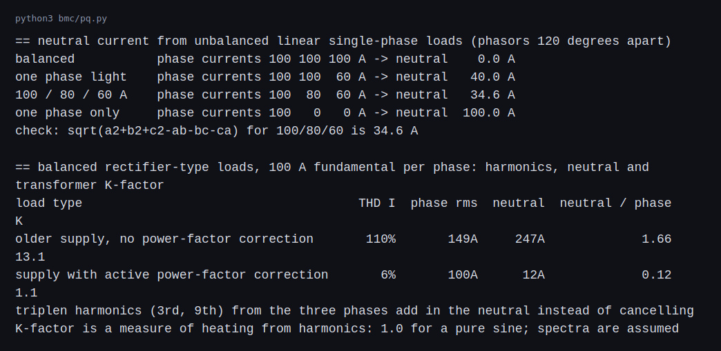
Balanced linear loads of 100 A put no current in the neutral. Phase currents of 100, 100 and 60 A put 40 A in it, and 100, 80 and 60 A put 34.6 A in it, which matches the closed form. One phase loaded alone puts 100 A in the neutral.
For balanced loads of the older supply type, with 100 A of fundamental per phase, the THD of the current is 110 percent and the phase current is 149 A rms. The neutral carries 247 A, which is 1.66 times the phase current. The K-factor is 13.1. For the supply with active power-factor correction the THD is 6 percent, the neutral carries 12 A and the K-factor is 1.1.
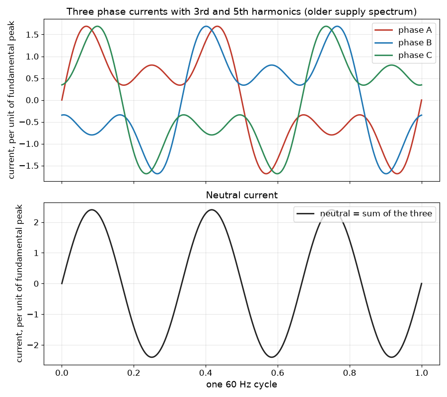
The upper plot shows the phase currents with their 3rd and 5th harmonics. The lower plot is their sum. The fundamental and the 5th cancel, and what is left is the 3rd harmonic at three times the amplitude of each phase’s 3rd, at 180 Hz.
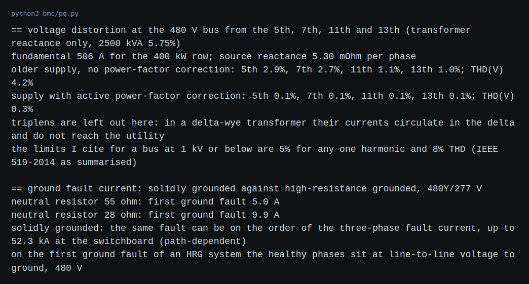
For the 400 kW row at 506 A of fundamental current, the older supply type gives a 5th harmonic voltage of 2.9 percent, a 7th of 2.7 percent and a THD of 4.2 percent at the 480 V bus, from the transformer reactance alone. The corrected supply gives 0.3 percent. The limits for a bus at 1 kV or below in IEEE 519-2014 are 5 percent for any one harmonic and 8 percent THD, a category the 2014 edition added because the secondary of the distribution transformer can now be a point of common coupling (PMI’s summary of the changes). The older type is inside them on these assumptions, with less margin. Other loads on the bus and the upstream source’s own distortion are not in the calculation, and a real study includes both.
With a 55 Ω neutral resistor the first ground fault is 5.0 A, and with 28 Ω it is 9.9 A. A solidly grounded system can carry a ground fault of the order of the three-phase fault current, up to 52.3 kA at the switchboard, depending on the path. On the first ground fault of a resistance-grounded system, the healthy phases sit at line-to-line voltage to ground, 480 V instead of 277 V.
Challenges
- Neutral overload is easy to miss. The neutral conductor usually has no breaker of its own, so a neutral carrying 1.66 times the phase current can overheat while every phase breaker looks normal. Oversized neutrals are used for loads like these.
- Changing the supplies changes the spectrum. Replacing older power supplies with ones that have power-factor correction cuts the harmonic current. A hall with a mix has a mix, and only measurement shows what it has.
- Extra neutral-ground bonds cause circulating current. A second bond downstream of the first, added in a panel or PDU, gives neutral current a parallel path through the grounding system. It is a wiring mistake that tends to appear after changes and shows up as noise or heating.
- A first ground fault in a resistance-grounded system does not trip anything. That is the point, because the load stays up, and it is also the risk. The fault has to be found and cleared before a second one on another phase turns it into a phase-to-phase fault.
- Transfer switches change the neutral. A switch that does not switch the neutral and one that does give different bonding arrangements, and the choice has to be consistent with where the neutral is bonded.
Differences with a production setup
Where a measurement, a standard, a datasheet or a vendor rating disagrees with a number in this post, the number in this post is the one that is wrong. The values most likely to differ are the two harmonic spectra, since a modern supply with active power-factor correction looks like the corrected one and not the older one, and the 55 ohm resistor, since a real high-resistance grounding resistor is sized from the system’s capacitive charging current and 5 A is a placeholder. The distortion limits come from a summary of IEEE 519-2014, not from the standard.
- Measurement. Real harmonic spectra come from a power quality analyzer on the actual loads. Mine are two chosen shapes, and an actual server mix is not one of them.
- Standards. NFPA 70, the NEC, covers grounding of separately derived systems in 250.30 and high-impedance grounded systems in 250.36. 250.36 applies at 480 V to 1,000 V. Eaton’s paper on neutral grounding quotes the earlier text, which allowed these systems where qualified persons service the installation, continuity of power is required, ground detectors are installed and line-to-neutral loads are not served, so a 277 V load needs a different arrangement (Eaton’s paper). The 2023 edition retitled it “Impedance grounded systems, 480 V to 1 kV” and opened it to other impedance types, and its note says the impedance is chosen to limit the ground-fault current to about the system’s capacitive charging current (EEPower).
- Distortion limits. IEEE Std 519 sets the limits, and the values I used match the table in PMI’s summary. In the 2014 edition the statistics are the 95th and 99th percentile values over 24-hour and seven-day periods, and the limits are not a single reading. The point of common coupling can be the utility connection and not the 480 V bus, and current limits apply there too.
- Grounding practice. IEEE Std 142, the Green Book, covers grounding of industrial and commercial power systems, and IEEE Std 1100, the Emerald Book, covers powering and grounding electronic equipment. Eaton’s paper takes its definitions of ungrounded, solidly grounded and resistance-grounded systems from the Green Book, and explains why high-resistance grounding keeps a facility running through a first ground fault while making the fault easier to locate than on an ungrounded system.
- Transformer ratings. Transformers are sold with K ratings and derating methods for harmonic loads. I computed a K-factor and applied no rating.
- Higher-frequency effects. Resonance with capacitors, skin effect and interharmonics are not in the model.
- Studies. A real design runs a harmonic study with the network, loads and capacitors modeled.
FAQ
Why does a balanced three-phase system have no neutral current?
The three currents are 120 degrees apart and have the same size, so they add up to zero at the neutral point.
Why do triplen harmonics add in the neutral?
The 3rd harmonic of each phase is shifted by three times 120 degrees, which is a whole number of cycles, so all three are in phase. In phase currents add instead of cancelling.
Why does it matter if a supply has power-factor correction?
Its input current is close to a sine, so it has little harmonic content. The example supply with correction put 12 A in the neutral against 247 A for the older type.
Why would a site ground through a resistor?
To keep running through a first ground fault and to limit the fault energy. The cost is that detection and a fast response become part of operations.
Why bond the neutral at one point only?
Bonding it again downstream gives the neutral current a second path through the grounding conductors and building steel.
What will change the most between this example and a real study?
The measured spectra and the protection design. A harmonic study uses the real harmonic content of the equipment, and a protection design uses real device data, so both replace the assumed values here.
Repeating with real hardware
Coming soon. A small power quality meter on a rack of real servers would show the real spectrum and the neutral current of one circuit.
Next
Take the quiz to test your understanding: Electrical series quiz
The next post in this series covers GPU load transients: a training load profile hitting a source and UPS model.
Comments