Goal
The GPU load post showed what a training load looks like to a source: a square wave every 1.5 seconds and a cliff when a checkpoint pauses the job. The on-site generation post chose the plant that has to carry it. This post puts the two together. What happens to the frequency of a gas plant when a block of load arrives at once? What does a battery have to do so the generators never see the fast part? How do a battery that forms the voltage and a generator that sets the frequency share a step? And what changes in protection and safety when part of the plant is an inverter?
We use the example site with its 20 halls and the same 105 MW plant, three 35 MW units online.
Terms used in this post
- Step load and load acceptance: a sudden change in load, and the amount a generator set can take in one step while staying inside its voltage and frequency limits.
- ISO 8528-5: the part of the generating set standard that defines transient performance classes G1 to G4 for voltage and frequency deviation and recovery after load steps.
- Droop: the slope of a governor that lowers the frequency as load rises so that parallel sources share load in proportion to their ratings.
- Inertia constant H: the kinetic energy stored in the rotating mass divided by the rating, in seconds. A larger H gives a slower frequency change.
- Grid-forming inverter: an inverter that behaves as a voltage source and sets its own voltage and frequency, with droop.
- Grid-following inverter: an inverter that behaves as a current source and tracks a voltage and frequency set by something else, usually with a phase-locked loop.
- Ride-through: staying connected and delivering through a disturbance.
- BESS: battery energy storage system, here with its inverter and enclosure.
- C-rate: discharge power divided by stored energy, per hour. A 1C battery empties in an hour.
- UL 9540, UL 9540A and NFPA 855: the product safety standard for energy storage systems, the fire propagation test method, and the installation standard.
What I built
bmc/stepload.py, a script with five parts: a per-unit swing-equation model of the plant with a prime mover lag, a battery that supplies the difference between the load and a filtered source, droop sharing between a grid-forming battery and the generators, ride-through energy for losing one unit, and the fault current of an inverter against a synchronous plant. A two-panel figure. The constants are assumed and marked A in the script. It is a textbook model and not an electromagnetic transient study.
How it works
What the plant sees
The hall post’s load swings 1,152 kW every 1.5 seconds per hall. If all 20 halls train in lock step, the site swings 23.0 MW at 0.67 Hz, from 46 MW to 23 MW of IT load, and a checkpoint pause drops it by 23 MW and holds it. This is the worst case, and a mixed hall with different jobs is smoother. We use the worst case because a design has to survive it.
The generator side
A generator set responds to a load step in three stages. The rotor slows, because the electrical power taken exceeds the mechanical power delivered, at a rate set by the inertia. The governor senses the frequency drop and asks for more fuel, with a slope set by the droop. The prime mover answers with a lag. The per-unit model is
2H d(Δf)/dt = Pm − Pl − D·Δf, with Pm following −Δf/R through a first-order lag of time constant Tg.
We use H of 1.5 s, droop R of 4 percent and Tg of 2 s on a 105 MW plant, all assumed. A gas engine or turbine is a slower prime mover than the load edge, so the frequency falls before the fuel catches up.
ISO 8528-5 is the standard that classes this behavior. It sorts generating sets into four performance classes, G1 to G4, for voltage and frequency deviation and recovery after load steps, with G4 left to agreement between the manufacturer and the customer. The numeric limits come from the standard and from the manufacturer’s declaration of the class a set meets, so a specification quotes them from there. Our model shows the shape of the response, not a class. The practical point is that acceptance criteria for a plant are written as a class, the load steps it must take and the deviation and recovery it must meet, and the load profile of a training cluster is part of that specification.
The battery side
A battery can take the fast part. If the source is asked to follow a filtered version of the load, the battery supplies the difference. A 10 s filter means the plant sees at most 2.3 MW per second and the battery sees the full 23 MW swing. The energy is small, 18 kWh, because the swing averages out over each cycle. The power is not small. That is the same result as the GPU load post, with a larger site: power-bound, not energy-bound.
A battery in this plant has three jobs with different sizes. Step-load buffering is power-heavy and energy-light. Ride-through covers a unit trip until a reserve starts. Power quality support, such as reactive power and harmonic filtering, is a function of the inverter more than of the cells.
Grid-forming and grid-following
NLR’s page on grid-forming inverter controls says that most inverter controllers today are grid-following and built on the assumption that system voltage and frequency are regulated by inertial sources, and that such approaches cannot guarantee stability in a low-inertia setting. A grid-following inverter controls the current it injects and needs a voltage and frequency to follow. A grid-forming inverter sets the voltage and frequency itself, usually with real power against frequency droop and reactive power against voltage droop.
The difference matters in an island. If the plant has only grid-following sources there is nothing to follow when the utility opens. A grid-forming battery can hold the voltage while generators start, which is the main reason it appears in a microgrid specification. Where the battery and the generators both have droop, they share a step in proportion to rating over droop.
IEEE 2800-2022 is the interconnection standard for inverter-based resources connected to transmission systems. A joint industry webinar describes it as applying to all inverter-based resources, including grid-forming ones, though designed with grid-following ones in mind. Its capability list includes voltage and frequency ride-through, active and reactive power control, frequency response, power quality and negative-sequence behavior. It is not enforceable until a regulator or grid operator adopts it.
Fault current
A synchronous generator delivers several times its rated current into a fault, set by its subtransient reactance. An inverter limits its current electronically, typically close to its rating. A plant that was protected assuming 5 to 6 per-unit of fault current may find that an island fed by inverters never reaches the pickup of its overcurrent relays. The microgrid post returns to this.
Battery safety
Three documents come up. UL 9540 is the foundational product safety standard for energy storage systems and equipment. UL 9540A is the standard test method for evaluating thermal runaway fire propagation. NFPA 855 is the standard for the installation of stationary energy storage systems. UL’s explainer says the 2026 edition of NFPA 855 adds Annex G.11 on large-scale fire testing and that edition 6 of UL 9540A has an effective date of 1 January 2027. UL is the author of its own test method, so we read its description as the owner’s.
Commands and results
python3 bmc/stepload.py step buffer share ride fault
python3 bmc/stepload.py plot stepload.png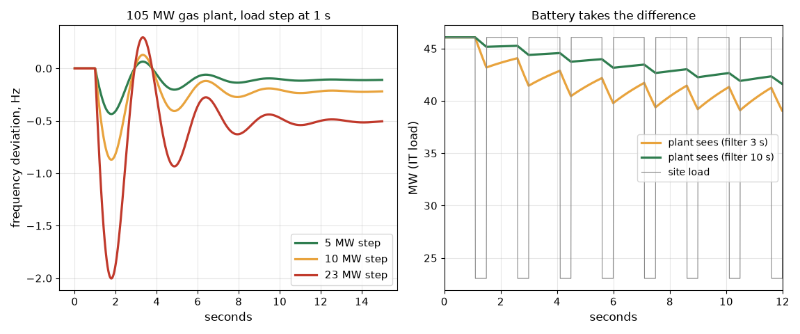
Steps. A load step on the 105 MW plant, with the assumed constants, gives a frequency nadir of 0.44 Hz below nominal for 5 MW, 0.87 Hz for 10 MW, 2.00 Hz for 23 MW and 3.48 Hz for 40 MW. The static droop values are 0.11, 0.23, 0.53 and 0.91 Hz. The nadir is about four times the static value because the prime mover lags the governor. The nadir comes within a second of the step, well before any fuel response arrives.
Buffer. The battery takes a peak of 23.0 MW with an energy swing of 18 kWh. A checkpoint pause drops the load 23 MW and holds it, and a 10 s filter ramps the plant down over about 30 s while the battery absorbs about 96 kWh. The generator never sees the cliff.
Sharing. A 30 MW grid-forming battery with 2 percent droop and 105 MW of generators with 4 percent droop split a 20 MW step as 7.3 MW to the battery and 12.7 MW to the generators, and frequency moves 0.29 Hz. The battery takes more per megawatt of rating because of its steeper characteristic.
Ride-through. Losing one derated 28.7 MW unit until a reserve starts and loads, an assumed 60 s, takes 478 kWh of battery energy at 28.7 MW, a 60C discharge. A one-hour battery of the same power holds 28.7 MWh, sixty times more than needed. Power, not energy, sizes it.
Fault current. A 105 MVA synchronous plant with a 0.17 subtransient reactance delivers about 5.9 per-unit, 618 MVA. A 36 MVA inverter current-limited at 1.2 per-unit delivers about 43 MVA, 7 percent of that.
Challenges
- Load steps arrive in the worst order. A checkpoint pause drops the load while the plant is at its most heavily loaded, and the job restarts at the same instant a generator is recovering. The step the plant must accept is the swing of the whole cluster, not of one hall.
- A battery state of charge is a constraint on the load. A battery at 100 percent cannot absorb a checkpoint drop and one at 0 percent cannot cover a step. Operations needs an alarm on state of charge band and a rule for what the controller does at the edges.
- Two sources with droop need matched settings. A battery whose droop and deadband do not match the generators will take all of a small step or none of it. Settings are verified in commissioning with the same load steps the model uses.
- Inverter limits change protection. An island fed by inverters has a fraction of the fault current of one fed by generators. Relay settings validated against the grid-connected case may not work in the island.
- Thermal runaway is a site design input. The battery enclosure, spacing, ventilation and fire suppression follow the fire test results and the installation standard and set how many megawatt-hours can sit in one place.
- Cycling wears the battery. A battery that buffers a 0.67 Hz swing does 57,600 small cycles a day, and chemistries differ in how they age under that duty. The GPU load post covers the cycle count and the choice of technology.
Production setup example
A generation specification for a training campus states the load profile the plant must accept, with the step size, the repetition rate and the checkpoint drop, and asks for a model of the response: frequency and voltage against time for each step with the plant’s controls. Acceptance is witnessed at the factory and again on site with load banks. The battery is specified by power, energy, response time, inverter mode (grid-forming where the plant must hold an island), the safety listings and the fire test report, and its inverter is modeled in the study tools the next posts describe.
The teaching numbers here come from a per-unit model with assumed constants. A real study uses the manufacturer’s governor and exciter models, the actual engine or turbine response, and a transient or electromagnetic study of the inverter controls.
FAQ
Why can’t a generator follow a training load?
The load changes in tens of milliseconds and the prime mover answers in seconds. The rotor’s inertia gives the governor time, but not enough for a step of a quarter of the plant rating.
What does ISO 8528-5 tell a buyer?
A class, G1 to G4, for the voltage and frequency deviation and recovery of a set after load steps. Buyers write the class and the steps into the specification and ask for a test.
Why does a battery need so little energy?
The swing goes up and down each cycle, so the net energy moved in one direction is small. The battery needs power for the edge and energy only for the area under the swing.
What is the difference between grid-forming and grid-following?
A grid-forming inverter sets voltage and frequency and shares load by droop. A grid-following inverter injects current into a voltage and frequency set by something else.
Why is inverter fault current a problem?
Protection that expects several times rated current may not trip on an inverter’s fault, which is limited near its rating.
What does this post not show?
A vendor curve, a governor model of a real set, an electromagnetic study or a fire test. It shows the size of the effects and the questions the specification must answer.
Repeating with real hardware
Coming soon. The nearest repeat is to run the same steps on a manufacturer’s published governor and generator model in a power-system study tool.
Next
Take the quiz to test your understanding: Electrical series quiz
The next post in this series covers microgrids: islanding, load shedding, black start and resynchronization.
Comments