Goal
Behind each rack is a run of copper that has to carry its current, stay within a voltage-drop budget and lose as little as possible as heat. Where power is delivered at 208 V, 415 V or 480 V changes all three. This post sizes one row of racks at each voltage and looks at what the choice does to the tap-off at each rack, to the busway above the row and to the number of transformers in the chain.
The short-circuit post ended at a rack breaker. This one starts there and works upstream along the row.
Terms used in this post
- Busway: a run of enclosed bars that carries power along a row, with openings where plug-in units connect, so racks can be added without new cables.
- Tap-off box: a plug-in unit on a busway with its own breaker that feeds one rack.
- Line-to-line voltage: the voltage between two phases, such as 208 V or 415 V.
- Line-to-neutral voltage: the voltage from one phase to neutral, the line-to-line value divided by the square root of three: 120 V on a 208 V system and 240 V on a 415 V one.
- Continuous load: a load expected to run for three hours or more. The common rule sizes the breaker at 125 percent of it, which is the same as loading it to 80 percent.
- Voltage drop: the voltage lost along a conductor, from current flowing through its resistance and reactance.
- Power factor: the ratio of real power in kW to apparent power in kVA, 0.95 here.
- PDU transformer: a transformer in a power distribution unit that steps 480 V down to 208Y/120 V for racks.
What I built
bmc/dist.py, a script that takes a rack or a row of racks and computes line current, the tap-off breaker, a busway rating, the voltage drop along it and the loss in it, at 208, 415 and 480 V three-phase.- A rack table for 10, 30, 50 and 100 kW racks.
- A row of ten 40 kW racks, 400 kW in total, on 30 m of busway, with the worst case of all the load at the far end.
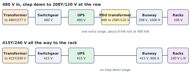
- A diagram of the two chains, one that steps down to 208Y/120 V and one that stays at 415Y/240 V.
How it works
Current. For a three-phase load, P = √3 × V × I × PF, so the line current is I = P / (√3 × V × PF). I used a power factor of 0.95 for all of it.
Tap-off. The breaker has to carry 125 percent of the continuous current. I rounded that up to the next standard rating in the NEC’s table of standard ampere ratings, Table 240.6(A) (EC&M). The 125 percent is the rule that sizes the overcurrent device at 125 percent of the continuous load, in 210.20(A) for branch circuits and 215.3 for feeders (EC&M).
Busway. I picked the next busway rating from an assumed set of catalog sizes, from 400 to 4,000 A, that covers 125 percent of the row current. The impedance of a busway is not something I could take from a data sheet, so I assumed 0.06 mΩ per metre of resistance and 0.04 mΩ per metre of reactance at 800 A and scaled both with the inverse of the rating. That is a rough rule for equal current density.
Voltage drop and loss. The drop is ΔV = √3 × I × (R cos φ + X sin φ) × L. With all the load at the far end it is a worst case, and with the racks spread evenly along the run the drop is about half. The loss in the busway is 3 × I² × R × L.
The chain. A 480 V system reaches 208Y/120 V through a transformer between the UPS and the row. A 415Y/240 V system gives 240 V from each phase to neutral, which many server power supplies accept, so the racks connect directly. The server data sheet decides this.
Commands and results
python3 bmc/dist.py rack
python3 bmc/dist.py row chain
python3 bmc/dist.py plot dist-current.png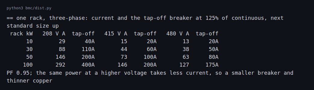
A 100 kW rack draws 292 A at 208 V, 146 A at 415 V and 127 A at 480 V. The tap-off breakers come out at 400 A, 200 A and 175 A. At 50 kW the 208 V rack needs a 200 A tap-off and the 415 V rack needs 100 A. Every doubling of the voltage halves the current and, in this table, roughly halves the breaker.
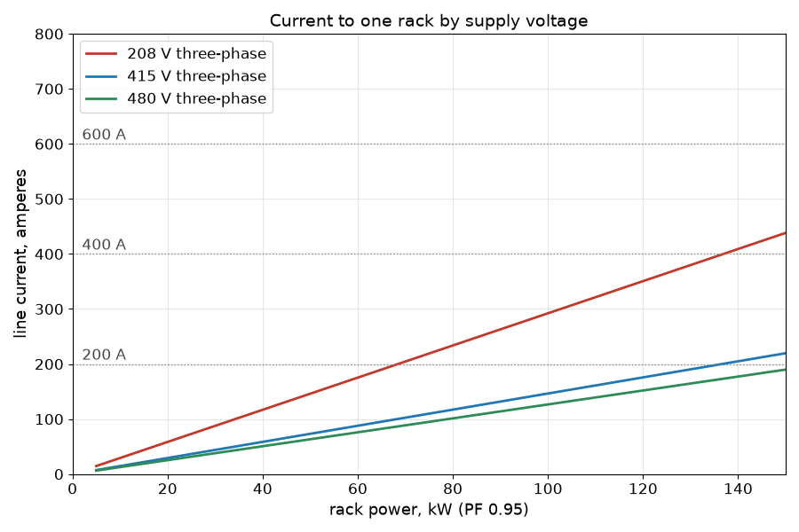
The three lines are straight because current is proportional to power at a fixed voltage. The dotted lines mark 200, 400 and 600 A. A 208 V rack crosses 200 A at about 70 kW. A 415 V rack reaches 200 A at about 137 kW.
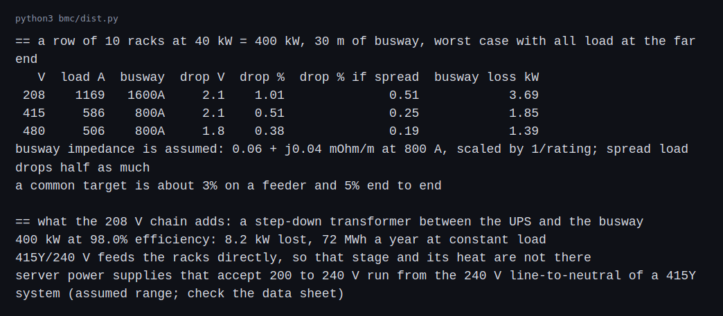
The row of 400 kW draws 1,169 A at 208 V, 586 A at 415 V and 506 A at 480 V. That needs a 1,600 A busway at 208 V and an 800 A busway at 415 V or 480 V. The end-loaded voltage drop is 2.1 V at both 208 V and 415 V, which is 1.01 percent of 208 V and 0.51 percent of 415 V. The loss in the busway is 3.7 kW at 208 V and 1.85 kW at 415 V. It halves and does not fall to a quarter, because the 208 V row gets a larger busway with lower resistance. That depends on my assumed impedance rule.
The step-down transformer is the larger difference. At an assumed 98 percent efficiency, 400 kW through a PDU transformer loses 8.2 kW, which is 72 MWh a year at constant load. That is more than twice the busway loss at 208 V, and the 415 V chain does not have it.
Busway ratings and factory-built distribution
Two limits on the busway are not in the script above, and a real selection starts with them. The busway impedance I assumed is a stand-in, and a manufacturer’s published impedance for the exact product replaces it. If the two differ, the published value is right and my drop and loss numbers are the ones to correct.
Short-circuit rating. A busway has to withstand the fault current available at its line end for as long as the upstream device takes to clear it. From the short-circuit post, the panel bus sees at most 17.0 kA. That is the upper bound from the textbook calculation, so a real busway rating has to be at or above it and above the value in the actual study. The duration is the part that gets missed. With an instantaneous trip, clearing takes about 0.025 s, 1.5 cycles. With the 0.2 s delay on the feeder in case B it is 12 cycles, and the energy the busway must withstand, I²t at 17.0 kA, goes from 7.2 to 57.8 kA²s, eight times as much. Busway short-circuit ratings are published by the manufacturer with the conditions they apply to, such as the type of upstream protection, and a rating given for fast clearing does not cover a delayed one. The same coordination trade-off as the switchboard in the earlier post applies, and the datasheet, not my table, is the authority.
Factory-built by nature. Busway is already a prefabricated product: straight lengths, elbows, tees and plug-in units are built to a drawing and assembled on site. Design for offsite manufacture is mostly about the interface:
- Lengths come from a survey. Runs are ordered from drawings or a field measurement, and a column or a pipe that moved after the order costs a custom length.
- Tap-off positions are a layout decision. Plug-in units are placed at fixed spacing along the run, and the rack layout has to match, or racks cannot land where the plugs are.
- Supports, expansion and fire stopping are the building’s side of the interface and need a coordinated drawing.
- Plug-in units can be added later, which is the reason to buy busway over fixed cable runs when the rack density is not known at the time of construction. The busway rating has to be sized for the final load, since the run itself is not changed.
Challenges
- Rack power rises faster than busway is replaced. A row planned for 10 kW racks gets 40 kW racks, and the busway rating, not the tap-off, becomes the limit. A tap-off box can be swapped in an afternoon. A busway that has to be replaced means an outage on the row.
- Phases drift out of balance. Plug-in units go onto whichever phase is nearest, and over time one phase carries more. The busway has to be sized for the heaviest phase, and the neutral current gets worse. The next posts return to this.
- The far end of the run loses the most voltage. Each rack added at the end lengthens the worst case. A drop that was 0.5 percent at commissioning can approach the budget when the row is full.
- Two voltages in one hall. A hall that mixes 208 V and 415 V racks needs separate busways, different connectors and clear labels, so a rack is never plugged into the wrong one.
- Joints heat when they loosen. Busway joints and plug-in connections that are not tight run hot, and they are commonly checked with infrared scans. The model has no thermal element; a thermographic survey under load during commissioning is how loose joints are found.
Differences with a production setup
Where a measurement, a standard, a datasheet or a vendor rating disagrees with a number in this post, the number in this post is the one that is wrong. The values most likely to differ are the busway impedance rule, the 98 percent transformer efficiency and the catalog sizes.
- Product data. Real busway has published impedance, ambient and altitude derating, short-circuit withstand ratings and fault-rated plug-in units. I assumed the impedance from one number and scaled it.
- Short-circuit rating. The previous section checks the energy against the earlier post’s fault current. A real selection uses the manufacturer’s tested rating for the product and the protection arrangement.
- Neutral and harmonics. Single-phase server loads on a three-phase system put current in the neutral, and nonlinear loads add to it. The neutral is sized in the grounding and power quality post, where harmonic content sets the current.
- Rules. NFPA 70, the NEC, has an article on busways and the continuous-load rule I used. The continuous-load rule is 210.20(A) and 215.3, as above. Other countries use IEC rules with different ratings.
- Power supplies. Which supplies accept 240 V line-to-neutral and what a 415 V design needs from the rack PDU depends on the equipment. The Open Compute Project publishes rack power designs that go beyond what I modeled.
- Transformer data. I assumed 98 percent efficiency. Real transformers have a published efficiency curve, and the loss depends on loading.
- Studies. Load-flow and voltage-drop studies for a real design use software with the real impedances of each segment.
FAQ
Why does a higher voltage mean a smaller breaker for the same power?
For three-phase power the current is the power divided by √3 times the voltage times the power factor. Doubling the voltage halves the current, so the same power needs half the breaker.
Why size the breaker at 125 percent of the load?
A breaker that carries its full rating for hours runs hot. The common rule for continuous loads leaves the breaker 25 percent above the load, which is the same as using 80 percent of its rating.
Why is the voltage drop in volts the same at 208 and 415 V?
The 208 V row carries twice the current on a busway with half the resistance. The product is about the same in volts, so the percentage is half at 415 V. That depends on how I scaled the busway.
Why does a 208 V chain have an extra transformer?
Large distribution runs at 480 V, and racks need 208Y/120 V. A transformer between them makes that step and loses some power as heat. A 415Y/240 V chain has racks that take 240 V from line to neutral, so it does not need it.
What will change the most between this example and a real design?
The component data. Real busway ratings, fault ratings and neutral sizing, and what each design costs, decide whether 415 V is the better choice for a given room.
Repeating with real hardware
Coming soon. A busway and tap-off boxes are not a home-scale purchase. The repeat is the same calculation on a manufacturer’s catalog data for a real row.
Next
Take the quiz to test your understanding: Electrical series quiz
The next post in this series covers UPS topologies and batteries: double conversion, line-interactive and eco mode, efficiency and runtime.
Comments